
Hardware reference guide

Pwr. & Grnding. Guide
794
35013379 02 October 2007
Modbus Plus
Grounding
Figure
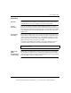
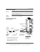
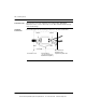
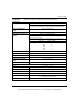
The following figure shows Modbus Plus grounding information.
Other Equipment
Grounding
Other equipment in the installation should not share the grounding conductor of the
system. Each piece of equipment should have its own grounding conductor
returning to the main grounding point from which the equipment power originates.
Systems with
Multiple Power
Feeds
In systems with multiple power feeds, the grounding should proceed in the same
manner as single feed systems. However, a zero volt potential difference must be
maintained between the equipment grounding conductors of the separate systems
to prevent current flow on communication cables.
Loop Clamp
(supplied with
Modbus Plus Tap)
Modbus Plus
Drop Cable
Remove outer
jacket to expose
the shield braid.
0.5 in
(13 mm)
min
11.8 in
(30 cm)
max
Existing backplane
ground screw may be
used if wire space
and clearance allows.
Ground
Screws
MB+
Use holes along backplane
mounting flange to secure clamp.
Customer electrical panel may
need to be drilled and tapped.
European compliance
To maintain CE compliance with the European Directive on EMC (89/336/EEC),
the Modbus Plus drop cables must be installed in accordance with these
instructions.
Failure to follow this instruction can result in injury or equipment damage.
CAUTION
This document provided by Barr-Thorp Electric Co., Inc. 800-473-9123 www.barr-thorp.com