
User guide

The MSTR Instruction
840 USE 115 00 Version 1.0
27
3.2.2 Representation
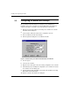
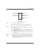
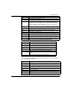
Figure 16 MSTR Block Structure
Inputs
The MSTR instruction has two control inputs:
the input to the top node enables the instruction when it is ON
the input to the middle node terminates the active operation when it is ON
Outputs
The MSTR instruction can produce three possible outputs:
the output from the top node echoes the state of the top input - it
g
oes ON
while the instruction is active
the output from the middle node echoes the state of the middle input - it
g
oes
ON if the MSTR operation is terminated prior to completion or if an error occurs
in completin
g
the operation
the output from the bottom node
g
oes ON when an MSTR operation has been
completed successfull
y
all outputs are zero indicates four MSTR instructions are alread
y
in pro
g
ress
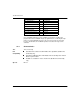
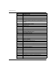
Top Node
Content
The 4
x
re
g
ister entered in the top node is the first of several
(
network dependent
)
holdin
g
re
g
isters that comprise the network
control block
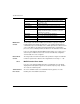
. The control block
structure differs accordin
g
to the network in use. For the TCP/IP Ethernet network
the control block structure is as follows:
control
block
data
area
MSTR
len
g
th
Enables selected
MSTR operation
Terminates active
MSTR operation
Operation is active
Operation terminated
unsuccessfull
y
Operation successful