
User guide

The MSTR Instruction
28
840 USE 115 00 Version 1.0
Middle Node
Content
The 4x re
g
ister entered in the middle node is the first in a
g
roup of conti
g
uous
holdin
g
re
g
isters that comprise the
data area
. For operations that provide the
communication processor with data such as a Write operation, the
data area
is the
source of the data. For operations that ac
q
uire data from the communication
processor, such as a Read operation, the
data area
is the destination for the data.
In the case of the Ethernet Read and Write CTE operations
(
see sections 3.2.11
and 3.2.12
)
, the middle node stores the contents of the Ethernet confi
g
uration
extension table in a series of re
g
isters.
Bottom Node
Content
The inte
g
er value entered in the bottom node specifies the
length
- the maximum
number of re
g
isters in the
data area
. The
length
must be in the ran
g
e 1 ... 100.
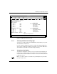
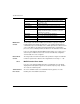
3.2.3 MSTR Function Error Codes
If an error occurs durin
g
an MSTR operation, a hexadecimal error code will be
displa
y
ed in the first implied re
g
ister in the
control block
(
the top node
)
. Function
error codes are network-specific.
TCP/IP Ethernet
Error Codes
An error in an MSTR routine over TCP/IP Ethernet ma
y
produce one of the
followin
g
errors in the MSTR
control block
:
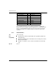
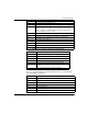
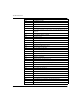
Register Content
Displayed
Identifies one of ten MSTR operations le
g
al for TCP/IP
(1 ... 4 and 7 ... 12).
First implied Displays error status.
Second implied Displays len
g
th (number of re
g
isters transferred).
Third implied Displays MSTR operation-dependent information.
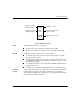
Fourth implied Hi
g
h byte: Destination index.
Low byte: Quantum backplane slot address of the web
embedded server module.
Fifth implied Byte 4 of the 32-bit destination IP Address.
Sixth implied Byte 3 of the 32-bit destination IP Address.
Seventh implied Byte 2 of the 32-bit destination IP Address.
Ei
g
ht implied Byte 1 of the 32-bit destination IP Address.