
User manual

Transferring Data Using Communication Blocks
180
33002479 06 07/2008
Control Block
Usage for SY/
MAX Ethernet
CTE Indicator
Implementation
(DATABUF)
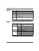
The values in the CTE table are displayed in the DATABUF output when a CTE read
operation is implemented. The registers display the following CTE data:
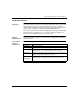
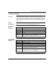
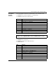
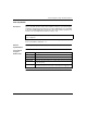
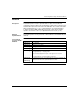
CTE indicator implementation (DATABUF):
Register Meaning
CONTROL[1] 11 = read CTE
CONTROL[2] Indicates the error status
CONTROL[3] Number of words transferred
CONTROL[4] Byte offset in the PLC register structure, specifying from where the CTE
bytes are read
CONTROL[5] Routing register
MSB: slot of the NOE module
CONTROL[6]
...
CONTROL[9]
Terminator: FF hex
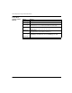
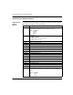
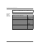
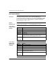
Parameter Register Contents
Frame type DATABUF[0] 1 = 802.3
2 = Ethernet
IP address DATABUF[1] First byte of the IP address
DATABUF[2] Second byte of the IP address
DATABUF[3] Third byte of the IP address
DATABUF[4] Fourth byte of the IP address
Lower netmask DATABUF[5] Most significant word
DATABUF[6] Least significant word
Gateway DATABUF[7] First byte of the gateway
DATABUF[8] Second byte of the gateway
DATABUF[9] Third byte of the gateway
DATABUF[10] Fourth byte of the gateway