
User manual

Transferring Data with the I/O Scanner
202
33002479 06 07/2008
Device Control
Block
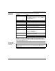
Important information about using the Device Control Block:
Registers The Device Control Block consists of registers either eight (8)
single words or four (4) double words. Contents of the registers
are mapped in the controller’s memory. Each bit corresponds to
an entry in the table (see the tables below.)
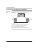
Disabling Devices Each I/O Scanner device can be disabled. To disable individual
devices:
1. Select the Device Control Block option on the I/O Scanner tab
in Unity Pro. (Insert a check mark in the box.)
2. Set the associated bit = 1.
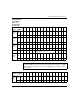
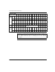
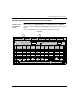
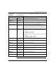
Mapping Device Control
Block Bits to I/O Scanner
Entry Numbers (#)
See the table for mapping entry numbers to bits.
Each entry number represents a logical device on the network.
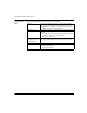
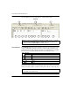
Setting Bits If Device Control Block bit is set to
z 0 = Device is enabled
z 1 = Device is disabled