
User manual

Transferring Data with the I/O Scanner
33002479 06 07/2008 203
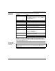
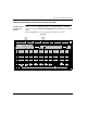
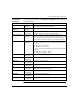
Mapping Device
Control Block
Bits to I/O
Scanner Entry
Numbers (#)
Single Word (W)
Register (%MDx:4)
W1
%MW
[x+1]
Table
Entry
#
1 2 3 4 5 6 7 8 9 10111213141516
Bit1514131211109876543210
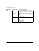
W2
%MW
[x+2]
Table
Entry
#
17 18 19 20 21 22 23 24 25 26 27 28 29 30 31 32
Bit1514131211109876543210
W3
%MW
[x+3]
Table
Entry
#
33 34 35 36 37 38 39 40 41 42 43 44 45 46 47 48
Bit1514131211109876543210
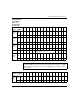
Word 4 through Word 7 (Table Entry 49
through 112)
W8
%MW
[x+8]
Table
Entry
#
113 114 115 116 117 118 119 120 121 122 123 124 125 126 127 128
Bit1514131211109876543210
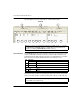
Note: Bits are counted from right to left starting from bit 0 (low bit). Examples: to
configure %MD1:4 as a device control block in the I/O Scanner table, use %MW2,
bit 15 to enable or disable table entry 1. Use %MW3, bit 15 to enable or disable
table entry 17.
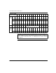
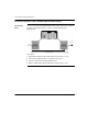
Double Word (DW)
Register (%MDx:4)
DW1
%MD
x[0]
Table
Entry
#
12345678910111213141516
Bit 31302928272625242322212019181716