
User manual


Implementing a Basic Application
150
SR2MAN01 11/2007
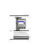
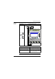
Presentation of Ladder Diagrams
Description In this section, we will use a simple example to understand how a ladder diagram
works: A two-way switch.
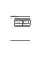
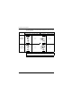
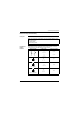
Normal electrical diagram Ladder diagram
The two position switches VV1 and VV2
control turning lamp L1 on and off.
I1 and I2 are two contacts representing inputs
1 and 2 on the smart relay.
Q1 is a coil that corresponds to output 1 from
the smart relay.
I1-i2----------[Q1
i1-I2