
User manual


Sample Application
SR2MAN01 11/2007 181
Implementing the Solution
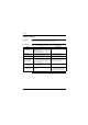
Description Presented here are the control diagrams to program, as well as the parameters to
use for the function blocks.
Implementing
the Ladder
Diagram
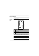
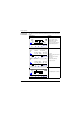
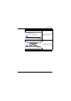
Below is the control diagram to program:
When upcounting and downcounting, the counter locks up when the car park
becomes full (no spurious detection or counting actions take place if vehicles are
allowed to enter by manual release).
In addition, output
Q2
is activated when entry into the car park is not allowed. This leads to the
use of an auxiliary relay to manually lock or unlock the access gate using the navigation keys.
Prompt Element
1 Counting vehicles in, subtracting vehicles out and manually updating the number
of vehicles actually in the car park.
2 Starting the lighting timer.
3 Starting the fan timer.
4 Handling the manual release function.
5 Outputs command: Car park full indicator, blocking the input, lighting the car park
and running the extraction fan.
Note: For a given counter, the coils CC and DC should only appear once in a
ladder diagram.
I1-H1-c1-------CC1
Z3
Z1---------
I2
I2-------------DC1
I3-------------TT1
I1
Z3
I4
Z4-------------SM2
Z2-------------RM2
A1-------------TT2
C1-------------[Q1
T2-------------[Q4
T1-------------[Q3
h1 m2----[Q2
1
2
3
4
5