
User manual


Implementing a Basic Application
SR2MAN01 11/2007 151
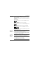
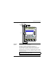
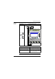
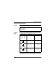
Module Wiring Below, an illustration of smart relay wiring:
Application
Operation
Using a smart relay means that ordinary switches (with open or closed positions)
can be used in place of two position switches.
The switches are identified as S1 and S2 in the wiring diagram above.
S1 and S2 are connected to inputs I1 and I2 on the smart relay.
The operating principle is as follows: Each time the status of inputs I1 and I2
changes, the status of output Q1 also changes which controls the lamp L1.
The ladder diagram uses basic functions, for example placing contacts in parallel
and in series, as well as the reverse function identified as i1 and i2 (see Using the
Reverse Function, p. 152).
Mon
N
Fuse 1
100 ... 240 VAC
50 / 60 Hz
S1
Fuse 2
L1
S2
MENU / OK
I2I1 I4I3 I6I5
100 ... 240 VDC
Inputs I1... I8 xx VDC
SRxxxxBD
Outputs
Q1 ... Q4: Relay 8A
12
Q1
12
Q2
12
Q3
12
Q4
NM
I8I7
Note: The implementation of a two-way switch is optimum when impulse relay coils
are used (see Discrete (DISCR) Outputs, p. 98).