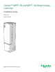
Conext™ MPPT 80 and MPPT 100 Solar Charge Controller Installation Guide 990-91319 February 2020 1 ! http://solar.schneider-electric.
Copyright © 2020 Schneider Electric. All Rights Reserved. Littelfuse is owned by Littelfuse Inc. Lexan is owned by Sabic. All other trademarks are owned by Schneider Electric Industries SAS or its affiliated companies.
Audience This manual is intended for use by qualified personnel installing a system involving Schneider Electric Conext MPPT 80 and MPPT 100 Solar Charge Controller. The qualified personnel have training, knowledge, and experience in: n Installing electrical equipment and PV and battery input systems (up to 1000 V). n Applying all applicable installation codes. n Analyzing and reducing the hazards involved in performing electrical work. n Selecting and using Personal Protective Equipment (PPE).
About This Guide Purpose This Guide provides explanations and procedures for installing and and troubleshooting the following Schneider Electric Conext MPPT Solar Charge Controllers: n Conext MPPT 80 600 Solar Charge Controller (80 A), part number: 865-1032 n Conext MPPT 100 600 Solar Charge Controller (100 A), part number: 865-1034 Scope This Guide provides safety guidelines, detailed planning and setup information, procedures for installing the charge controller, and information about troubleshooting.
Abbreviations and Acronyms CEC Canadian Electric Code CSA Canadian Standards Association DC Direct Current FCC Federal Communications Commission GFP Ground Fault Protection IMP Current at maximum power per STC ISC Short circuit current rating of an PV panel under STC LCD Liquid Crystal Display LED Light Emitting Diode MPP Maximum Power Point MPPT Maximum Power Point Tracking MSDS Material Safety Data Sheet NFPA National Fire Protection Association PDP XW Power Distribution Panel PV
Related Information You can find information about operating the charge controller in the Conext MPPT 80 and MPPT 100 Solar Charge Controller Owner's Guide. It is provided with the charge controller and is also available at solar.schneiderelectric.com. You can find more information about Schneider Electric as well as its products and services at solar.schneider-electric.com.
Safety Information Conext MPPT 80 and MPPT 100 Installation Guide Safety Information Important Information Read these instructions carefully and look at the equipment to become familiar with the device before trying to install, operate, service or maintain it. The following special messages may appear throughout this documentation or on the equipment to warn of potential hazards or to call attention to information that clarifies or simplifies a procedure.
Conext MPPT 80 and MPPT 100 Installation Guide Safety Information Safety Information n Before using the charge controller, read all instructions and cautionary markings on the unit, the batteries, and all appropriate sections of this manual. n Use of accessories not recommended or sold by the manufacturer may result in a risk of fire, electric shock, or injury to persons. n The charge controller is designed to be permanently connected to your AC and DC electrical systems.
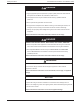
Safety Information Conext MPPT 80 and MPPT 100 Installation Guide DANGER HAZARD OF ELECTRIC SHOCK, EXPLOSION, ARC FLASH, AND FIRE n Apply appropriate personal protective equipment (PPE) and follow safe electrical work practices. See NFPA 70E, CSA Z462, or EN 50110-1. n This equipment must only be installed and serviced by qualified electrical personnel. n Never operate energized with covers removed n Energized from multiple sources.
Conext MPPT 80 and MPPT 100 Installation Guide Safety Information Battery Safety Information DANGER HAZARD OF ELECTRIC SHOCK, BURN, FIRE, AND EXPLOSION Batteries contain corrosive electrolyte and can give off explosive gases. Battery circuits present a shock and energy hazard. Observe proper precautions when working with batteries and battery circuits, including: n Always wear eye protection when working with batteries. n Wear rubber gloves and boots when handling batteries.
Safety Information Conext MPPT 80 and MPPT 100 Installation Guide FCC Information to the User This charge controller has been tested and found to comply with the limits for a Class B digital device, pursuant to part 15 of the FCC Rules and Industry Canada ICES-003. These limits are designed to provide reasonable protection against harmful interference when the charge controller is operated in a residential environment.
Conext MPPT 80 and MPPT 100 Installation Guide Contents Audience 2 Purpose 3 Scope 3 Abbreviations and Acronyms 4 Related Information 5 Safety Information 6 Safety Information Battery Safety Information FCC Information to the User 9 10 Introduction 18 Features 19 Charge Controlling 20 Conext MPPT 80 600 20 Conext MPPT 100 600 20 Configurations 20 Typical Installation Installation 20 22 Required Materials and Tools 23 Required Accessories 23 PV Array Requirements 23 Mount
Conext MPPT 80 and MPPT 100 Installation Guide Commissioning 44 Troubleshooting 50 Troubleshooting Replacing the Ground Fault Protection Fuse 53 Ground Faults in a Normally Ungrounded Array 53 Specifications Electrical Specifications 56 57 MPPT Voltage Range 58 Operating Below the PV Array Voltage Full Power Range 59 Conext MPPT 80 600 59 Conext MPPT 100 600 59 Default Battery Charging Settings 60 Mechanical Specifications 61 Output Power Versus Ambient Temperature 62 Accessories 6
Conext MPPT 80 and MPPT 100 Installation Guide Figures Figure 1 Typical Installation 21 Figure 2 Minimum Clearance Requirements 26 Figure 3 Removing the wiring compartment cover 26 Figure 4 Wiring Compartment with Lexan Barrier 27 Figure 5 Knockout dimensions 28 Figure 6 Dimensions and knockout locations 28 Figure 7 Mounting the Charge Controller 29 Figure 8 Chassis ground connector 30 Figure 9 DC Terminal Connector Locations 31 Figure 10 Typical Wiring Diagram for a Negative-Grounded Sys
Conext MPPT 80 and MPPT 100 Installation Guide Tables 990-91319 Table 1 Minimum clearance requirements 25 Table 2 Troubleshooting 51 Table 3 Electrical specifications 57 Table 4 Mechanical specifications 61 This document is for use by qualified personnel 16
Introduction Conext MPPT 80 and MPPT 100 Installation Guide 1 Introduction What's in This Chapter? Features 19 Charge Controlling 20 Conext MPPT 80 600 20 Conext MPPT 100 600 20 Configurations 20 Typical Installation 20
Conext MPPT 80 and MPPT 100 Installation Guide Introduction Features The Conext MPPT 80 or MPPT 100 Solar Charge Controller (charge controller) tracks the maximum power point of a PV array to deliver the maximum available current for optimum charging of batteries. The charge controller can be used with 24 VDC and 48 VDC battery systems only. Key product features include a 600 VDC maximum input voltage, a Fast Sweep™ MPPT tracking algorithm, and built-in ground fault protection.
Introduction Conext MPPT 80 and MPPT 100 Installation Guide Charge Controlling Conext MPPT 80 600 The Conext MPPT 80 600 charge controller regulates the PV array current at an appropriate level for 24 or 48 V batteries. It can produce up to 80 amps of charging current for both 2400 watts at 30 V or 4800 watts at 60 V. Conext MPPT 100 600 The Conext MPPT 100 600 charge controller regulates the PV array current at an appropriate level for 24 or 48 V batteries.
Conext MPPT 80 and MPPT 100 Installation Guide Introduction Figure 1 Typical Installation Conext SCP Conext XW+ or Conext XW Pro Conext PDP Conext MPPT 80 600 or MPPT 100 600 CB* Conduit Box + PV Array - + - + - + - Battery Bank *CB = 100 A for Conext MPPT 80 600 125 A for Conext MPPT 100 600 21 This document is for use by qualified personnel 990-91319
Installation Conext MPPT 80 and MPPT 100 Installation Guide 2 Installation What's in This Chapter? Required Materials and Tools 23 Required Accessories 23 PV Array Requirements 23 Mounting 24 Choosing a Location 24 Removing the Wiring Compartment Cover 26 Removing Knockouts 27 Mounting the Charge Controller 28 PV Grounding 29 Chassis Grounding 29 Internal Ground Fault Protection 30 Wiring 31 Connector Locations 31 Wire Size and Over-current Protection Requirements 31 Connecti
Conext MPPT 80 and MPPT 100 Installation Guide Installation DANGER HAZARD OF ELECTRIC SHOCK, EXPLOSION, ARC FLASH, AND FIRE Installation of this equipment should only be planned and performed by qualified personnel in accordance with all applicable installation codes. See "Audience" on page 2 for the definition of qualified personnel. Failure to follow these instructions will result in death or serious injury.
Installation Conext MPPT 80 and MPPT 100 Installation Guide Each charge controller must be connected to its own PV array. Up to three PV array strings can be connected in parallel to a single charge controller. See Connecting Multiple PV Array Strings to One Unit on page 37. WARNING HAZARD OF ELECTRIC SHOCK AND FIRE n The PV array voltage must never exceed 600 V in any condition (open circuit, cold temperature, bright sun, etc.).
Conext MPPT 80 and MPPT 100 Installation Guide Installation WARNING HAZARD OF EXPLOSION Do not install the charge controller in a sealed compartment containing batteries. Failure to follow these instructions can result in death, serious injury, or equipment damage. NOTICE CHARGE CONTROLLER DAMAGE The charge controller can overheat if installed in a sealed, indoor enclosure. Do not install the charge controller in a sealed compartment. Failure to follow these instructions can result in equipment damage.
Installation Conext MPPT 80 and MPPT 100 Installation Guide Figure 2 Minimum Clearance Requirements Removing the Wiring Compartment Cover DANGER HAZARD OF ELECTRIC SHOCK, EXPLOSION, ARC FLASH, AND FIRE Before removing the wiring compartment cover, make sure all electrical power sources have been disconnected for at least two minutes. Before energizing the charge controller, make sure the wiring compartment cover has been replaced and all fasteners are in place.
Conext MPPT 80 and MPPT 100 Installation Guide Installation through the wiring compartment. In this scenario, you must take care to avoid intermingling the high voltage PV and low voltage battery wires. Figure 4 Wiring Compartment with Lexan Barrier Lexan barrier Removing Knockouts Fourteen knockouts are provided for conduit or cable entry into the charge controller (see Figure 5 and Figure 6): n Three single (one on each side and one on the back) for battery wires: 1.73 in. (44.0 mm).
Installation Conext MPPT 80 and MPPT 100 Installation Guide 719.0 (28.3) Figure 5 Knockout dimensions Ø 44.0 (1.73) KNOCKOUT 150.0 (5.9) Ø 35.0 (1.38) KNOCKOUT 2PL Ø 28.2 (1.11)/ Ø 22.2(0.87) DUAL KNOCKOUT 102.5 (4.03) 82.8 (3.26) 131.5 (5.18) Ø 6.5 (0.25) 2PL (1.03) (1.14) (1.78) (2.17) (3.37) 35.0 (1.38) 22.8 (0.90) 66.5 (3.52) 62.3 (2.45) 22.8 (0.90) 26.4 29.0 45.4 55.2 85.5 85.0 (3.35) 110.0 (4.33) 169.0 (6.
Conext MPPT 80 and MPPT 100 Installation Guide Installation 1. Remove the wiring compartment cover (see Figure 3). 2. Mark the location of the keyhole slot on the wall. 3. Secure the top mounting screw in the location marked, but leave the screw head backed out approximately ¼ inch (6 mm). 4. Place the charge controller onto the screw and pull it down into the keyhole slot. 5. Insert two screws in the two mounting holes provided to secure the charge controller to the wall.
Installation Conext MPPT 80 and MPPT 100 Installation Guide mm2)1 . Internal Ground Fault Protection The charge controller utilizes different ground fault protection for grounded and ungrounded arrays. If the charge controller detects a ground fault, it ceases operating and indicates a fault on the charge controller’s display and over the Xanbus network. The charge controller is configured at the factory for an ungrounded PV array.
Conext MPPT 80 and MPPT 100 Installation Guide Installation Wiring The following sections provide information about wiring. Connector Locations Terminal connectors for DC wiring are located inside the wiring compartment. Labels above the DC wiring terminals identify all the connection points. See Figure 9. Figure 9 DC Terminal Connector Locations XANBUS XANBUS BTS AUX BATTERY _ + NEG. GND PV. PV- TERMINAL TORQUE POS. GND PV. PV+ TERMINAL TORQUE 25 lbf.in (2.8 Nm) 15 lbf.in (1.
Installation Conext MPPT 80 and MPPT 100 Installation Guide Over-current Protection WARNING HAZARD OF ELECTRIC SHOCK, ENERGY, AND FIRE Over-current protection must be provided, external to the unit, to protect the battery wiring. External disconnecting means must also be provided for both the PV and battery circuits. Consult applicable electrical codes to establish the correct fuse or circuit breaker ratings and for required locations of protection and disconnecting means.
Conext MPPT 80 and MPPT 100 Installation Guide Installation array is used, then a 60A switch may be required. Schneider Electric offers the following options: n 600V 30A, Square D HU361 n 600V 60A, Square D HU362 n 600V 64A, Schneider Electric MPPT Disconnect RS (865-1036), offers two channels at 32A each. Each string must not exceed 25.
Installation Conext MPPT 80 and MPPT 100 Installation Guide Connecting the Charge Controller The following procedure is illustrated in Figure 10. DANGER HAZARD OF ELECTRIC SHOCK Whenever a PV array is exposed to light, a shock hazard exists at the output wires or exposed terminals. Open the array disconnect switch before making the connections. Failure to follow these instructions will result in death or serious injury. To connect the charge controller in a negative-grounded system: 1.
Conext MPPT 80 and MPPT 100 Installation Guide n Installation For positive-grounded systems, the PV array disconnect switch must be in the negative conductor. n For floating systems, the PV array disconnect switch must be a 2-pole type disconnect, connected in both the positive and negative conductors as per applicable electrical code in the United States and Canada. In general, the same rules apply for disconnect switches as for battery circuits: they must be located in all ungrounded conductors.
Installation Conext MPPT 80 and MPPT 100 Installation Guide Figure 10 Typical Wiring Diagram for a Negative-Grounded System (48 V Battery Bank Shown) 1 2 4800 W STC array (2 x 2400 W strings) BAT PV - PV + CHASSIS GROUND To inverter 100 ADC (typical) Disconnect (configuration will vary) 48 V battery bank Ground LEGEND Ground DC Positive DC Negative Circuit Breaker NOTE: n The positive or negative of the battery can be grounded independent of the array grounding.
Conext MPPT 80 and MPPT 100 Installation Guide Installation Connecting Multiple PV Array Strings to One Unit The charge controller has two three-pole PV connectors, allowing up to three PV array strings to be directly connected in the charge controller. These input connectors can accept #6 to #14 AWG (13.5 to 2.5 mm2) solid or stranded wire. WARNING HAZARD OF FIRE n As per applicable electrical codes, fuses are required when paralleling (combining) more than two PV strings.
Installation Conext MPPT 80 and MPPT 100 Installation Guide Connecting Multiple Units In a multiple-unit installation, each charge controller must be connected to one or more separate PV arrays. See Figure 11. For other multiple-unit installation considerations, see Network Installation on page 39. NOTICE PV ARRAY AND CHARGE CONTROLLER DAMAGE Make sure that each charge controller is correctly connected to its own PV array(s) and that no wires are interconnected between charge controllers.
Conext MPPT 80 and MPPT 100 Installation Guide Installation WARNING HAZARD OF ELECTRIC SHOCK AND FIRE The auxiliary NO and NC dry contacts are rated up to 60 VDC and up to 8 A. Do not expose the auxiliary contacts to voltages or currents higher than this rating. Provide external overcurrent protection rated at 8 A maximum. Failure to follow these instructions can result in death, serious injury, or equipment damage.
Installation Conext MPPT 80 and MPPT 100 Installation Guide n n Xanbus-enabled devices: l Conext MPPT 80 or MPPT 100 Solar Charge Controller l Conext XW+ or Conext XW Pro Inverter/Charger l Conext Automatic Generator Start l Conext System Control Panel or Conext Gateway l MPPT Disconnect RS Xanbus power supply—an embedded power supply in the charge controller provides up to 7 W of power to the Xanbus network to power one SCP and AGS, not including the auxiliary supply.
Conext MPPT 80 and MPPT 100 Installation Guide Installation Figure 14 Network layout 1 Network terminator 2 Charge Controller cable 3 Cable to next device Connecting Network Cables Between Multiple Units WARNING HAZARD OF ELECTRIC SHOCK Do not route the network cables with the same conduit or panel as the PV or battery input and output cables, and make sure the network cables are not intermingled with other conductors in those systems.
Installation Conext MPPT 80 and MPPT 100 Installation Guide 4. Route the cable to charge controller #2. 5. Connect the network cable to a network port in charge controller #2. 6. Connect another network cable to charge controller #2, and then route the cable to the next device in the network. 7. Make sure the factory-supplied network terminators are inserted into the empty network ports in the devices at the beginning and end of the network.
Conext MPPT 80 and MPPT 100 Installation Guide Installation 1. Remove the charge controller’s wiring compartment cover (see Removing the Wiring Compartment Cover on page 26). 2. Remove a knockout from the back or either side of the charge controller, and then install an appropriately-sized strain relief bushing for the BTS cable. 3.
Installation Conext MPPT 80 and MPPT 100 Installation Guide Figure 16 Installing the BTS 1 + – 2 + + – + – – 1 Insert the BTS plug into the charge controller’s BTS port. 2 Attach the BTS to a battery terminal or to the side of a battery. 6. Replace the charge controller’s wiring compartment cover. Commissioning Conext SCP You must use the SCP to commission the charge controller.
Conext MPPT 80 and MPPT 100 Installation Guide Installation Before you begin, make sure you have all important system information such as the nominal battery voltage, battery type, and battery bank capacity available. To commission one or more charge controllers: 1. Setting the Device Number on page 45 2. Configuring Connections and Charger Settings on page 46 3. If commissioning multiple charge controllers:Copying Settings to Another Charge Controller on page 47 4.
Installation Conext MPPT 80 and MPPT 100 Installation Guide charge controllers, the manufacturer recommends using 01 for the first charge controller. 9. Press Exit until the Select Device menu is displayed. The charge controller appears as XW MPPT80 xx or XW MPPT100 xx on the menu, where xx is the device number that you selected. 10. Repeat steps 3 through 9 if you are commissioning multiple charge controllers.
Conext MPPT 80 and MPPT 100 Installation Guide Installation type, you can further configure bulk, absorption, float, and other settings for the charge cycle in the Custom Settings menu that appears. 9. While in the Chgr menu, make sure the nominal battery voltage (Batt Voltage) is set correctly. The default value is 48 V. If your system is a 24 V battery system, then change it to 24 V. 10. Press Exit until the Select Device menu is displayed.
Installation Conext MPPT 80 and MPPT 100 Installation Guide which you want to copy. Scroll to select the charge controller with the device number that matches the first charge controller you configured, and then press Enter again. The settings are automatically copied from the selected charge controller. NOTE: The Copy from command will not give you any indication that it has completed its task.
Troubleshooting Conext MPPT 80 and MPPT 100 Installation Guide 3 Troubleshooting What's in This Chapter? Troubleshooting 51 Replacing the Ground Fault Protection Fuse 53 Ground Faults in a Normally Ungrounded Array 53
Conext MPPT 80 and MPPT 100 Installation Guide Troubleshooting Troubleshooting DANGER HAZARD OF ELECTRIC SHOCK, EXPLOSION, ARC FLASH, AND FIRE This chapter includes tasks that must be performed only by qualified personnel equipped with appropriate personal protective equipment and following safe electrical work practices. Review the Safety Information on page 7 before proceeding. Failure to follow these instructions will result in death or serious injury.
Troubleshooting Conext MPPT 80 and MPPT 100 Installation Guide A. Use the SCP to configure the charge controller for 24 V operation. See “Configuring Battery The charge controller’s A. The default configuration for the charge Characteristics and Battery Charging” in the Conext Error/ Warning (red) controller is a 48 V battery bank, and you MPPT 80 and MPPT 100 Owner's Guide for more LED is on, and the SCP have installed the charge controller on a 24 V information.
Conext MPPT 80 and MPPT 100 Installation Guide The charge controller’s On/Charging (green) LED is flashing. Troubleshooting No problem. This is intended operation. See The charge controller is outputting charge “Viewing Status Information on the Solar Charge current. Controller” in the Conext MPPT 80 and MPPT 100 Owner's Guide for LED status information.
Troubleshooting Conext MPPT 80 and MPPT 100 Installation Guide On a normally ungrounded (floating) array, the ground fault protection system indicates a fault when a short circuit or lower than normal resistance exists between the array and ground. Before resetting the fault and attempting to restart the system, it is important to have qualified service personnel, such as a certified electrician or technician, determine the cause of the ground fault and effect repair.
Specifications Conext MPPT 80 and MPPT 100 Installation Guide A Specifications What's in This Chapter? Electrical Specifications 57 MPPT Voltage Range 58 Operating Below the PV Array Voltage Full Power Range 59 Conext MPPT 80 600 59 Conext MPPT 100 600 59 Default Battery Charging Settings 60 Mechanical Specifications 61 Output Power Versus Ambient Temperature 62 Accessories 63 Conext System Control Panel 63 Conext Gateway 63 Conext Config Tool 63 Regulatory Approvals 64
Conext MPPT 80 and MPPT 100 Installation Guide Specifications Electrical Specifications Note: All specifications are subject to change without notice.
Specifications Conext MPPT 80 and MPPT 100 Installation Guide Note: n PV array voltages often exceed STC voltage specifications, especially when the array is cold. At cold temperatures the open circuit voltage will be higher than at STC or MPPT operating points. Refer to data provided by the maker of the PV panels and ensure the maximum voltage can never exceed the limits in the table above.
Conext MPPT 80 and MPPT 100 Installation Guide Specifications Operating Below the PV Array Voltage Full Power Range When the charge controller is used on a 48 V battery bank and a PV array where the MPP is below 230 V, full output power is not assured. The figures below show the maximum output current and maximum output power that can be produced when the charge controller is operating below 230 V.
Specifications Conext MPPT 80 and MPPT 100 Installation Guide Default Battery Charging Settings All settings in the following table are based on a 48 V nominal battery bank at 25°C (77°F). For a 24 V nominal battery bank, divide the voltage values in this table by two. Battery Type Setting Flooded1 Gel AGM Equalize Voltage 64.0 V n/a n/a ReCharge Voltage 50.0 V 50.0 V 50.0 V Bulk Voltage 57.6 V 56.8 V 57.2 V Absorption Voltage 57.6 V 56.8 V 57.2 V Float Voltage 54.0 V 55.2 V 53.
Conext MPPT 80 and MPPT 100 Installation Guide Specifications Mechanical Specifications Table 4 Mechanical specifications IP20, indoor, ventilated, aluminum sheet metal chassis with 7/8" and 1" (22.22 mm Enclosure Type and 27.76 mm) knockouts and aluminum heat sink Maximum and Minimum Wire Size in Conduit Maximum and Minimum Wire Size Rating of PV Terminal Block Maximum and Minimum Wire Size Rating of Battery Terminal Block Wire Size Rating of Auxiliary Output Connector #6 AWG to #14 AWG (13.5 to 2.
Specifications Conext MPPT 80 and MPPT 100 Installation Guide Output Power Versus Ambient Temperature Once the charge controller’s heat sink reaches maximum full-power operating temperature, the charge controller reduces its power output to ensure component ratings are not exceeded. Figure 20 Output power vs. ambient temperature, Conext MPPT 80 600 Thermal Dera!ng for MPPT 80-600 7000 max Power )W) 6000 5000 4000 3000 2000 1000 0 -20 0 20 40 60 80 Ambient Temp (°C) Figure 21 Output power vs.
Conext MPPT 80 and MPPT 100 Installation Guide Specifications Accessories Conext System Control Panel The Conext System Control Panel (SCP) (Part Number 865-1050) is required for installation of the charge controller and is strongly recommended for ongoing operation. As the primary interface to the charge controller, the SCP is used for setup and configuration. Once installation is complete, you can use the SCP for monitoring and fault reporting.
Specifications Conext MPPT 80 and MPPT 100 Installation Guide Regulatory Approvals Certified to UL 1741 and to CSA 107.1 and carries the c(CSA)us mark.
Schneider Electric As standards, specifications, and designs change from time to time, please ask for confirmation of the information given in this publication. For other country details please contact your local Schneider Electric Sales Representative or visit the Schneider Electric Solar Business website at: http://solar.schneider-electric.com/ © 2020 Schneider Electric. All Rights Reserved.