
Installation Guide


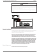
Table Of Contents
- Audience
- Safety Information
- Introduction
- Installation
- Troubleshooting
- Specifications

mm2)
1
.
Internal Ground Fault Protection
The charge controller utilizes different ground fault protection for grounded and
ungrounded arrays. If the charge controller detects a ground fault, it ceases operating and
indicates a fault on the charge controller’s display and over the Xanbus network. The
charge controller is configured at the factory for an ungrounded PV array.
Grounded Arrays
For grounded arrays, the charge controller has two PV ground fault protection fuse
holders (rated 600 VDC, 1 A maximum) located inside the wiring compartment.
Ungrounded (Floating) Arrays
For ungrounded (floating) arrays, the charge controller detects the impedance between
the array and ground, and it indicates a fault if the resistance is too low.
DANGER
HAZARD OF ELECTRIC SHOCK, EXPLOSION, ARC FLASH, AND FIRE
n Do not ground either PV conductor outside of the unit.
n Grounded arrays: Install a fuse in the correct holder: (+) or (–). Replace the fuse with
the same type and rating (Littelfuse KLKD 1 or equivalent). Fuses must be replaced by
qualified service personnel only.
n Ungrounded (floating) arrays: Leave both fuse holders empty.
Failure to follow these instructions will result in death or serious injury.
Figure 8Chassis ground connector
Chassis ground
terminals (4)
Ground fault
This symbol identifies the
protective conductor
(grounding) connection.
holders
protection fuse
1
Based on the NEC (NFPA 70) Article 250 for 100 A maximum battery fuse.
Installation Conext MPPT 80 and MPPT 100 Installation Guide
990-91319 This document is for use by qualified personnel 30