
Installation Guide


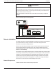
Table Of Contents
- Audience
- Safety Information
- Introduction
- Installation
- Troubleshooting
- Specifications

Connecting the Charge Controller
The following procedure is illustrated in Figure 10.
DANGER
HAZARD OF ELECTRIC SHOCK
Whenever a PV array is exposed to light, a shock hazard exists at the output wires or
exposed terminals. Open the array disconnect switch before making the connections.
Failure to follow these instructions will result in death or serious injury.
To connect the charge controller in a negative-grounded system:
1. Make sure the PV array disconnect and battery disconnect are turned off.
2. Install a cable clamp into each knockout being used.
NOTICE
REVERSE POLARITY DAMAGE
Before energizing the charge controller from either the PV array or from the battery,
check the polarity of all power connections. Positive (+) must be connected to positive
(+). Negative (–) must be connected to negative (–).
Failure to follow these instructions can result in equipment damage.
3. Ground the charge controller: connect a grounding conductor between a charge
controller ground lug and the grounding electrode (see Figure 10).
4. Connect the PV array’s negative (–) output to the charge controller terminal marked
PV –.
5. Connect the PV array’s positive (+) output to the PV array disconnect.
6. Route another positive (+) cable from the other end of the PV array disconnect to the
charge controller terminal marked PV +.
7. Connect the negative (–) battery cable to the charge controller terminal marked BAT
–.
8. Connect a positive (+) cable from the charge controller terminal marked BAT + to the
battery disconnect.
9. Connect a second positive (+) cable from the other side of the battery disconnect to
the positive (+) battery terminal.
10. Torque the charge controller’s battery terminals to 25 lbf.in (2.8 Nm) and the PV
terminals to 15 lbf.in (1.7 Nm). Allow some slack on the cables within the charge
controller and secure the wiring with strain reliefs or cable clamps.
To connect the charge controller in a positive-grounded or floating system:
◆ Follow the same steps described above for a negative-grounded charge controller
installation except modify the location of the PV array disconnect switch as follows:
Installation Conext MPPT 80 and MPPT 100 Installation Guide
990-91319 This document is for use by qualified personnel 34