
Installation Guide


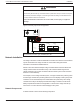
Table Of Contents
- Audience
- Safety Information
- Introduction
- Installation
- Troubleshooting
- Specifications

WARNING
HAZARD OF ELECTRIC SHOCK AND FIRE
The auxiliary NO and NC dry contacts are rated up to 60 VDC and up to 8 A. Do not expose
the auxiliary contacts to voltages or currents higher than this rating. Provide external over-
current protection rated at 8 A maximum.
Failure to follow these instructions can result in death, serious injury, or equipment
damage.
Figure 12 Auxiliary output vent fan application
-
+
BATTERY
+
_
NEG. GND PV.
PV- PV+
POS. GND PV.
XANBUSXANBUS BTS AUX
TERMINAL TORQUE
25 lbf.in (2.8 Nm) 15 lbf.in (1.7 Nm)
TERMINAL TORQUE
Aux terminals (from left to right): COMMON | NO | NC
Network Installation
The charge controller is a Xanbus-enabled device. Xanbus is a network communications
system which allows the charge controller to communicate settings and status
information to other Xanbus-enabled devices.
Xanbus connections between multiple charge controllers allow information about each
charge controller and its associated PV array to be communicated among all of the
charge controllers in the system. Information about the entire system can be viewed on
the SCP or Conext Gateway.
For example, in a two-charge controller system, if charge controller #1 is producing 1500
W and charge controller #2 is producing 2000 W, the SCP displays a total system power
of 3500 W. The accumulated amp hours and kilowatt hours produced by each charge
controller for that day is also displayed. Networked charge controllers can also share
battery temperature information if a single BTS is connected to a charge controller (or
Conext XW+ or Conext XW Pro Inverter/Charger) in the system.
Network Components
A Xanbus network consists of the following components:
Conext MPPT 80 and MPPT 100 Installation Guide Installation
39 This document is for use by qualified personnel 990-91319