
Installation Guide
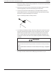
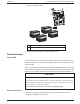

Table Of Contents
- Audience
- Safety Information
- Introduction
- Installation
- Troubleshooting
- Specifications

n Xanbus-enabled devices:
l Conext MPPT 80 or MPPT 100 Solar Charge Controller
l Conext XW+ or Conext XW Pro Inverter/Charger
l Conext Automatic Generator Start
l Conext System Control Panel or Conext Gateway
l MPPT Disconnect RS
n Xanbus power supply—an embedded power supply in the charge controller provides
up to 7 W of power to the Xanbus network to power one SCP and AGS, not including
the auxiliary supply.
To reduce tare losses at night, you can configure the charge controller to shut off the
Xanbus power supply after sunset. See “Disabling Power Supplies at Night” in the
Conext MPPT 80 and MPPT 100 Owner's Guide for more information.
n Network cables—each Xanbus-enabled device is connected by a standard Ethernet
(CAT 5/CAT 5e) patch cable. Do not use crossover cable.
n Network terminators (see Figure 13)—the Xanbus network must be properly
terminated at each end to help ensure communication signal quality.
Network terminators plug into network ports on Xanbus-enabled devices. The charge
controller ships with one terminator. Depending on your network layout, this
terminator might need to be inserted into another device elsewhere in the network.
Two network terminators are required for all Xanbus network configurations.
Figure 13 Network terminator
Network Layout
Xanbus-enabled devices are connected with separate lengths of cable. The devices at
each end of the chain must have a terminator inserted into their open network ports, as
shown in Figure 14. Total cable length for the Xanbus network must not exceed 131 feet
(40 m).
Installation Conext MPPT 80 and MPPT 100 Installation Guide
990-91319 This document is for use by qualified personnel 40