
Installation Guide
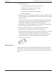
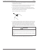
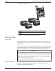
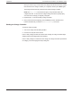

Table Of Contents
- Audience
- Safety Information
- Introduction
- Installation
- Troubleshooting
- Specifications

Figure 14 Network layout
1 Network terminator
2 Charge Controller cable
3 Cable to next device
Connecting Network Cables Between Multiple Units
WARNING
HAZARD OF ELECTRIC SHOCK
Do not route the network cables with the same conduit or panel as the PV or battery input
and output cables, and make sure the network cables are not intermingled with other
conductors in those systems.
Failure to follow these instructions can result in death, serious injury, or equipment
damage.
Dual knockouts on the back and sides of the charge controller are provided for routing the
Xanbus network cable (see Figure 5 on page 28). See Figure 9 on page 31 for the location
of the charge controller’s network ports.
NOTICE
RISK OF EQUIPMENT DAMAGE
n Connect only Xanbus-enabled devices. Although the cabling and connectors used in
this network system are the same as ethernet connectors, this network is not an ethernet
system.
n Do not connect one end of the network to the other to make a ring or loop.
Failure to follow these instructions can result in equipment damage.
To connect network cables between multiple charge controllers:
1. Remove the wiring compartment cover from each charge controller (see Removing
the Wiring Compartment Cover on page 26).
2. Remove a knockout from the back or either side of the unit, and then install an
appropriately sized strain relief bushing for the network cable.
3. Connect the network cable to a network port in charge controller #1.
Conext MPPT 80 and MPPT 100 Installation Guide Installation
41 This document is for use by qualified personnel 990-91319