
Schneider Electric Conext Combox Owners Guide
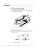

Installation
2–8 975-0679-01-01 Revision E
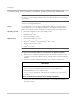
Modbus versus
Xanbus
The RS 485 Modbus connection and Xanbus cable connection provide data
communication from the network and devices to the Conext ComBox.
Communication with Modbus devices is handled through the RS 485 or 10/100
Ethernet connection on the Conext ComBox while communication with Xanbus
components occurs through the Xanbus ports of Xanbus-enabled devices.
Connecting the
Conext ComBox
with other Modbus
Devices
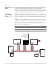
In a Modbus implementation, the Conext ComBox can act as a master or slave to
an RS 485 master device. The RS 485 connection to the Conext ComBox allows
communication between the Xanbus network and the third- party device. This
enables Conext devices to link to third-party software and building management
systems.
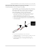
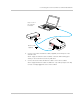
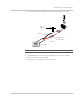
If a Modbus device, including the Conext ComBox, is installed as the last device
in a daisy chain, a 120 ohm terminator must be used because they do not have
an internal terminator for the RS 485 network. When inserting two wires in one
terminal, as in the case of daisy-chained RS 485 Modbus devices, use smaller
gauge wires. See the following example.
Note: Turn off all Modbus and other devices prior to wiring the connectors.
Note: A common ground line (0V) between all Modbus devices is also required.
24 V
Power
Supply
See NOTE below.
Modbus
Device 1
RS 485
120-ohm
Terminator
Modbus
Device 2
Modbus
Device 3
Modbus
Device 4
RS 485
120-ohm
Terminator
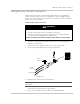
Connect the
RS 485 connector
to the Combox RS
485 port.
D1
D0
Shield