
Conext SW 4048-120 Manual Addendum

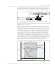
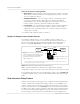
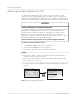
Table Of Contents

Documentation Update
4 976-0315-01-01 Rev E
allows the CSW to support local loads by converting excess power from external
DC sources connected to its battery bank. Examples of external DC sources are
MPPT solar charge controllers. When local loads demand more energy from the
external DC sources then extra current can be pulled in from the AC source as a
last resort. When operating without a solar charge controller in the system, set
the battery charge cycle to 2StgNoFloat to allow AC Support to function
immediately after the absorption charge stage.
AC Support behaves three different ways depending on the type of equipment
that is installed in the Xanbus network with the CSW.
• SOC - Xanbus-enabled battery monitor is installed
• Enhanced - Xanbus-enabled MPPT solar charge controller is installed
• Regular - neither Xanbus-enabled battery monitor nor MPPT solar charge
controller is installed
AC Support Mode using SOC
With AC support on SOC (AC Supp on SOC) enabled, CSW maximizes power
utilization using stored energy in a battery bank within a grid-interactive backup
power system. AC support mode allows the CSW to accurately determine when
grid power can be used to supply energy to the loads by knowing the state-of-
charge (SOC) of the battery bank.
The SOC of a battery bank is monitored by using a Xanbus-enabled battery
monitor. SOC entry and exit points are determined by the user. The SOC entry
point (AC Supp Start Soc) which is a high percentage value determines when
AC support mode is engaged and the SOC exit point (AC Supp Stop Soc) which
is a low percentage value determines when AC support mode is disengaged.
See “AC Support Mode Setting” on page 16.
Enhanced AC Support
Enhanced AC Support (EnhancedACSup) works when power systems are DC
coupled with a Xanbus-enabled MPPT Solar Charge Controller. This means that
DC power from a renewable source such as an MPPT Solar Charge Controller is
used to charge the battery bank while simultaneously utilizing its power (by way
of inverting) to power loads. Entry and exit to enhanced AC support are
Figure 2 AC Support Mode using SOC
Battery
Monitor
Conext SW
Battery
Bank
SCP
AC Loads
AC OUTAC IN
DC
Grid
NOTE: Entry and exit into AC Support
Mode is determined by the SOC. In this
case, AC support mode is engaged.
15 A< 2 A*
> 13 A
SOC Entry = 80%
actual SOC = 75%
SOC Exit = 50%
* To prevent injecting current into the grid from the inverter, there is less than 2 amps of offset allowed
from the grid to flow into AC IN under all conditions.