
Conext SW 4048-120 Manual Addendum

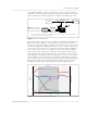
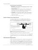
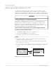
Table Of Contents

Documentation Update
6 976-0315-01-01 Rev E
Enhanced AC Support Charging Stages
• BULK Phase - During this phase, all PV energy from the charge controller is
diverted to the battery for maximum charging. During this phase, the CSW
does not engage AC support.
• ABSORPTION Phase - Once the charge controller is in absorption phase,
the charge controller output is split between the battery and CSW for
supporting AC loads. As the battery approaches full charge, more power
from the charge controller is diverted to CSW for AC support.
• FLOAT Phase - Once the battery is full and the charge controller transitions
to float phase, almost all the charge controller output is used by CSW to
support AC loads. The battery only receives a trickle charge to maintain a
healthy state of charge.
See “Enhanced AC Support Setting” on page 17.
Regular AC Support without Xanbus devices
If no Xanbus-enabled devices, such as an MPPT charge controller, are
connected to the power system, then entry and exit into AC support mode is
based solely on battery voltage monitored by CSW. If the battery voltage is
above a set limit (AC Supp Volts), then AC support mode is engaged.
With its charger enabled, the CSW enters AC support mode only after
completing a charge cycle when it is first powered up or reconnected to the grid.
For regular AC support mode set the CSW’s battery charge cycle to 2StgNoFloat
to allow AC Support feature to function immediately after the absorption charge
stage.
Grid-Interactive Delay Feature
CSW has a delay feature that postpones the engagement of two grid-interactive
features, namely load shaving and AC support, until a connected MPPT solar
charge controller has had a chance to charge the battery for two hours in Float
mode. The delay feature is called PLSDelay in SCP. The delay feature prioritizes
the MPPT solar charge controller’s ability to sufficiently charge the battery bank.
The feature works by inhibiting grid-interactive operation for two hours from the
time the charge controller transitions from Absorption to Float charging. This
Figure 5 Regular AC Support without Xanbus Devices
Conext SW
Battery
Bank
SCP
AC Loads
AC OUTAC IN
DC
Grid
NOTE: Entry and exit into AC Support Mode
is determined by the battery voltage. In this
case, AC support mode is engaged because
actual battery voltage is above the AC
support voltage level.
actual battery voltage = 25V
AC support voltage = 24V
15 A
< 2 A*
> 13 A
* To prevent injecting current into the grid from the inverter, there is less than 2 amps of offset allowed
from the grid to flow into AC IN under all conditions.