
Schneider Electric C35 User Manual


Installation
44 975-0004-01-02 Rev D
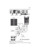
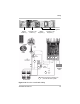
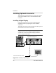
PV Charge Control Mode Wiring
The procedure below is illustrated in Figure 2-23.
To connect the C-Series controller as a charge controller:
1. Connect the PV array’s positive (+) output to the PV
array disconnect.
2. Route another (+) cable from the other end of the RE
disconnect to the
PV GFP.
3. Route another (+) cable from the same switch in the PV
GFP to the terminal marked
PV POS/LOAD in the C-Series
controller.
4. Connect the PV array’s negative (–) output to the
terminal marked C
OMMON NEGATIVES.
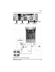
5. Connect another negative (-) cable from the other
C
OMMON NEGATIVES to the Negative bus in the DC
disconnect.
6. Route a negative (–) wire from the PV GFP to the
Negative bus in the DC disconnect.
7. Connect a positive (+) cable from terminal marked BAT
POS to the battery disconnect in the DC disconnect.
8. Connect a second positive (+) cable to the other side of
the battery disconnect in the DC disconnect and connect
to the positive (+) battery terminal.
9. Connect the negative (–) battery cable to the negative bus
in the DC disconnect and tighten the lugs.
10. Tighten per torque requirements outlined on page 39.
Allow a little slack on the cables within the controller and
secure the wiring with strain reliefs.
WARNING: Shock Hazard
PV arrays generate voltage whenever light strikes the surface of the
array. Before connecting the C-Series controller, cover or
disconnect the array to prevent any current from being generated.