
User manual


18
Part D – System Planning and Design
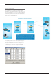
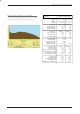
Common Cable Types Loss per meter Loss per 10m
@ 450MHz @ 450MHz
RG58C/U 0.4426dB 4.4dB
RG213/U 0.1639dB 1.6dB
FSJ1-50 (¼” superflex) 0.1475dB 1.5dB
LDF4-50 (1/2” heliax) 0.0525dB 0.52dB
LDF5-50 (7/8” heliax) 0.0262dB 0.3dB
Data Connectivity
The V24 Standard
The E Series radio modems provide two asynchronous
V24 compliant RS232 ports for connection to serial data
devices.
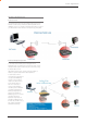
There are two types of RS232 interfaces – DTE and DCE.
DTE stands for data terminal equipment and is generally
applied to any intelligent device that has a need to
communicate to another device via RS232. For example:
P.C. Comm ports are always DTE, as are most PLC and RTU
serial ports.
DCE stands for data communication equipment and is
generally applied to a device used for sending data over
some medium (wires, radio, fibre etc), i.e. any MODEM.
The standard interface between a DTE and DCE device
(using the same connector type) is a straight through
cable (i.e. each pin connects to the same numbered
corresponding pin at the other end of the cable).
The “V24” definition originally specified the DB25
connector standard, but this has been complicated by
the emergence of the DB9 (pseudo) standard for asynch
devices, and this connector standard has different pin
assignments.
The wiring standard is “unbalanced”, and provides for
three basic data transfer wires (TXD, RXD, and SG – signal
ground).
Hardware Handshaking
Hardware handshake lines are also employed to provide
flow control, however (in the telemetry industry) many
devices do not always support all (or any) flow control lines.
For this reason, the E Series modems can be configured for
full hardware flow control, or no flow control at all (simple 3
wire interface).
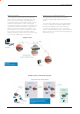
Note: that when connecting devices together with differing
handshake implementations, it is sometimes necessary
to “loop” handshake pins in order to fool the devices
handshaking requirements.
In telemetry applications (particularly where port speeds
can be set to the same rate as the radio systems over-air
rate) then flow control, and therefore handshaking, is usually
NOT required. It follows that any devices that CAN be
configured for “no flow control” should be used in this mode
to simplify cabling requirements.
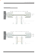
Handshaking lines can generally be looped as follows:
DTE (terminal) – loop RTS to CTS, and DTR to DSR and
DCE.
DCE (modem) - loop DSR to DTR and RTS (note-not
required for E Series modem when set for no handshaking).
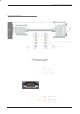
RF Feeders and Protection
The antenna is connected to the radio modem by way
of an RF feeder. In choosing the feeder type, one must
compromise between the loss caused by the feeder, and
the cost, flexibility, and bulk of lower loss feeders. To do this,
it is often prudent to perform path analysis first, in order to
determine how much “spare” signal can be allowed to be
lost in the feeder. The feeder is also a critical part of the
lightning protection system.
All elevated antennas may be exposed to induced or direct
lightning strikes, and correct grounding of the feeder and
mast are an essential part of this process. Gas discharge
lightning arresters should also be fitted to all sites.
Note: All ETSI installations require the use of a lightning
surge arrestor in order to meet EN6095. See Part A -
Preface for lightning arrestor specifications.