
User manual

49
Disabled
This selection disables the DCD output on the port.
This selection is not permissible if hardware based flow
control has been selected.
RF Carrier Detect
This selection causes DCD to be asserted at the onset of
a an RF signal that is higher than the mute setting. This
will generally occur several milliseconds before data is
transmitted from the port.
Data Detect (RS485 Flow Control)
This selection causes DCD to be asserted when data is
about to be transmitted from the port. This option is not
available if handshaking is set to “None” or “Xon/Xoff”.
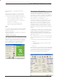
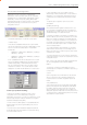
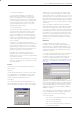
RF Parameters
This section of the main window permits adjustment
of transmitter and receiver, radio channel modulation
scheme, frequency trim and advanced features.
Transmitter
The transmitter can be configured for transmit frequency
and power level.
Frequency
The required transmit frequency in MHz can be entered
in the display field. The programmer checks that the
selected frequency is in the range for the particular
model of radio and provides warnings if it is not.
Power Adjust
The currently selected transmit power is displayed below
the button in dBm. The power level can be adjusted by
selecting this button which displays a dialogue box. The
up/down keys, or a typed in value, can be used to select
the required power level in dBm steps. There are two
methods for setting the power.
Part I – TVIEW+ Management Suite - Programmer
• CTS
The CTS is a signal from the modem to the host
informing the host that the modem is able to accept
incoming data on the TXD line. It responds to the
actions of the RTS line similar to the operation of a
“standard” line modem.
The CTS is FALSE if the RTS line is FALSE. Once
the RTS line is set to TRUE (signalling that the host
wants to send some data to the modem on the TXD
line), then the CTS will be set TRUE within 1ms, if the
modem is capable of accepting more data.
The CTS line will be set to FALSE if the transmit
buffer in the modem exceeds 4075 bytes, or the
number of queued frames exceeds 29 to ensure
that no overflow condition can occur.
• RTS
The RTS line is used for two reasons. The first is to
assert the CTS line in response to RTS. The RTS line
can also be used to key up the transmitter stage of
the modem.
• DTR
The DTR line is used for flow control of data being
sent from the modem to the host controller. When
the host is able to accept data it sets this line to
TRUE, and if data is available within the modem, it
will be sent to the host. If the host cannot accept
any more data, then it sets the DTR to FALSE, and
the modem will stop all transmissions to the host.
• Xon/Xoff
If the flow control mechanism is XON/XOFF then
the modem uses the standard ASCII control codes
of DC1 {^Q=11(Hex)=17(Dec)} for XON and DC3
{^S=13(Hex)=19(Dec)} for XOFF. The DTR input line
is totally ignored.
Note: There is no substitution mechanism employed
in the XON/XOFF protocol, so care must be taken
when transferring binary data to ensure that invalid
flow control characters are not generated.
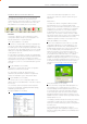
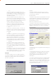
Advanced
This button provides access to the advanced features
of the port configuration. When selected a dialogue box
appears which permits selection of the source for the
port DCD output signal.