
Installation Guide


4-EN © 2011 Schneider Electric All Rights Reserved
ENGLISH
TYPICAL WIRING DIAGRAMS
Notes:
1. For HVAC systems with a single transformer for heating and cooling, leave the metal jumper
between Terminal 1 (RC) and Terminal 2 (RH) on the left terminal strip must in place. See Figure 3.
2. The EER56000 thermostat is factory-configured to control a single stage conventional HVAC
system.
If the HVAC system is a heat pump or a dual fuel heat pump, before operating the thermostat
configure the “System Type” settings under “System Options.” See “Setup and Configuration” on
page 13.
3. When configured as a conventional thermostat, by default this thermostat does not turn the fan on
with a call for heat. If the furnace requires the thermostat to turn the fan on with a call for heat,
configure the “System Mode” to “Fan On With Heat” under “System Options.”
4. A conventional thermostat can be configured for automatic changeover heat/cool, manual
changeover heat/cool, heat only, or cool only thermostat. Refer to the “Configuration” steps
associated with the wiring diagram for the HVAC system type.
5. If the thermostat or HVAC system does not perform as stated in the “Power Up” steps under the
wiring diagram for the HVAC system type, recheck all wiring. See Troubleshooting on page 19.
6. For HVAC systems with separate heating and cooling transformers, remove the metal jumper
between Terminal 1 (RC) and Terminal 2 (RH) on the left terminal strip. See Figure 4 on page 5.
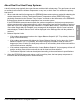
Figure 3: Test and Configuration Power-up
24 Vac "HOT"
24 Vac Common
24 VAC
CONTROL
TRANSFORMER
THERMOSTAT
UP
1
3
(C)
(RC)
JUMPER
2
For HVAC systems with a single transformer for
heating and cooling, leave the metal jumper
between Terminal 1 (RC) and Terminal 2 (RH) in
place.