
Instructions / Assembly


2-EN © 2011 Schneider Electric All Rights Reserved
ENGLISH
Before installing this thermostat:
1. Read this Installer’s Guide and the User’s Guide, document number S1B14479.
2. Ensure that this thermostat is suitable for the application.
3. Ensure that the wiring complies with all applicable codes and ordinances.
4. Turn off control transformer power.
5. Use a properly rated voltage sensing device to confirm that power is off.
Location
When replacing an existing thermostat, install the EER56000 thermostat in the same location. If the
location does not meet the following criteria, choose a new location:
1. Ensure that the thermostat is mounted 5 ft. above the floor and is at least 2 ft. from an exterior wall.
2. Ensure that the thermostat is located in an area with adequate air circulation.
3. Do not mount the thermostat in the path of direct sunlight or radiant heat generated by appliances.
4. Do not mount the thermostat on an exterior wall, near a fireplace, or in the path of any air ducts.
Removing an existing thermostat
1. Turn off control transformer power.
2. Use a properly rated voltage sensing device to confirm that power is off.
3. Remove the cover of the thermostat.
4. Disconnect the wires going to each terminal on the thermostat. Label each wire with the letter or
number at the terminal.
5. Remove the plate or base from the wall.
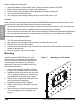
Mounting
Install the optional EER5700 trim ring if the
thermostat you are replacing is larger than the
new one. Follow the instructions supplied with
the trim ring for mounting the trim ring and
thermostat. If you are not installing a trim ring,
follow these instructions.
1. Hold the thermostat by the sides, avoiding
the keys, and unsnap the base from the face.
2. Holding the base to the wall so that the word
“UP” is upright and facing you, mark the two
mounting holes on the wall using a pencil.
3. Using a 3/16 in. diameter drill bit, drill a hole
at the mounting hole markings.
4. Install the two wall anchors supplied.
5. Slide the system wires through the opening
in the base.
6. Mount the base to the wall using the two #6 x
1/2 in. self-tapping screws supplied. See
Figure 1.
Figure 1: Mounting the Thermostat