EM3555 Bi-Directional Compact Power and Energy Meter Installation Guide ZL0093-0A 11/2011
EM3555 HAZARD CATEGORIES AND SPECIAL SYMBOLS ZL0093-0A 11/2011 Read these instructions carefully and look at the equipment to become familiar with the device before trying to install, operate, service or maintain it. The following special messages may appear throughout this bulletin or on the equipment to warn of potential hazards or to call attention to information that clarifies or simplifies a procedure.
EM3555 Contents ZL0093-0A 11/2011 CONTENTS © 2011 Schneider Electric All Rights Reserved. Safety Precautions............................................................................................... 1 Installation Overview............................................................................................ 1 Specifications....................................................................................................... 2 Introduction......................................................
EM3555 Contents ZL0093-0A 11/2011 ii © 2011 Schneider Electric All Rights Reserved.
EM3555 Safety Precautions ZL0093-0A 11/2011 SAFETY PRECAUTIONS DANGER HAZARD OF ELECTRIC SHOCK, EXPLOSION, OR ARC FLASH • Follow safe electrical work practices. See NFPA 70E in the USA or applicable local codes. • This equipment must only be installed and serviced by qualified electrical personnel. • Read, understand, and follow the instructions before installing this product. • Turn off all power supplying equipment before working on or inside the equipment.
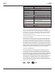
EM3555 Specifications ZL0093-0A 11/2011 SPECIFICATIONS Table 1 Specifications Type Description Measurement Accuracy Real Power and Energy IEC 62053-22 Class 0.5S, ANSI C12.20 0.5% Reactive Power and Energy IEC 62053-23 Class 2, 2% Current 0.4% (+0.015% per °C deviation from 25°C) from 5% to 100% of range; 0.8% (+0.015% per °C deviation from 25°C) from 1% to 5% of range Voltage 0.4% (+0.
EM3555 Specifications ZL0093-0A 11/2011 Type Description Environmental Conditions Operating Temperature -30° to 70°C (-22° to 158°F) Storage Temperature -40° to 85°C (-40° to 185°F) Humidity Range <95% RH (non-condensing) Altitude of Operation 3 km max.
EM3555 Introduction ZL0093-0A 11/2011 INTRODUCTION The EM3555 DIN Rail Power Meter provides a solution for measuring energy data with a single device. Inputs include Control Power, CTs, and 3-phase voltage. The EM3555 supports multiple output options, including solid state relay contacts, Modbus, data logging, and pulse. The LCD screen on the faceplate allows instant output viewing. The EM3555 Meter is capable of bidirectional metering.
EM3555 Dimensions ZL0093-0A 11/2011 DIMENSIONS Figure 2 EM Series Dimensions Meter Housing 1.8” (45 mm) 1.9” (48 mm) 2.3” (59 mm) 1.5” (39 mm) 3.6” (91 mm) 4.2” (107 mm) Bottom View (DIN Mount Option) 4.2 “ (107 mm) 3.6 “ (91 mm) 0.2 “ (4 mm) Bottom View (Screw Mount Option) 2.4 “ (61 mm) 1.2 “ (31 mm) + + 0.3 “ (8 mm) 3.9“ (99 mm) 4.3 “ (109 mm) + © 2011 Schneider Electric All Rights Reserved. 0.
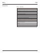
EM3555 Data Output ZL0093-0A 11/2011 DATA OUTPUT Table 2 Data Output Full Data Set (FDS): Signed Power: real, reactive, and apparent 3-phase total and per phase Real and Apparent Energy Accumulators: import, export, and net; 3-phase total and per phase Reactive Energy Accumulators by Quadrant: 3-phase totals and per phase Configurable for CT & PT ratios, system type, and passwords Diagnostic alerts Current: 3-phase average and per phase Volts: 3-phase average and per phase line-line and line-neutral Pow
EM3555 Installation ZL0093-0A 11/2011 INSTALLATION NOTE: Observe correct CT orientation. The meter can be mounted in two ways: on standard 35 mm DIN rail or screw-mounted to the interior surface of the enclosure. A. DIN Rail Mounting 1. Disconnect and lock out power. Use a properly rated voltage sensing device to confirm power is off. 2. Attach mounting clips to the underside of the housing by sliding them into the slots from the inside.
EM3555 Supported System Types ZL0093-0A 11/2011 SUPPORTED SYSTEM TYPES The meter has a number of different possible system wiring configurations (see Wiring Diagrams). To configure the meter, set the System Type via the User Interface or Modbus register 130. The System Type tells the meter which of its current and voltage inputs are valid, which are to be ignored, and if neutral is connected.
EM3555 Wiring ZL0093-0A 11/2011 WIRING DANGER HAZARD OF ELECTRIC SHOCK, EXPLOSION, OR ARC FLASH • Apply appropriate personal protective equipment (PPE) and follow safe electrical work practices. See NFPA 70E in the USA or applicable local codes. • This equipment must only be installed and serviced by qualified electrical personnel. • Turn off all power supplying equipment before working on or inside the equipment. • Always use a properly rated voltage sensing device to confirm power is off.
EM3555 Wiring Diagrams ZL0093-0A 11/2011 WIRING DIAGRAMS WARNING RISK OF ELECTRIC SHOCK CT negative terminals are referenced to the meter’s neutral and may be at elevated voltages · Do not contact meter terminals while the unit is connected · Do not connect or short other circuits to the CT terminals Failure to follow these instructions can result in death or serious injury.
EM3555 Control Power ZL0093-0A 11/2011 CONTROL POWER Direct Connect Control Power (Line to Neutral) Direct Connect Control Power (Line to Line) L1 L2 L3 G 1 2 N L1 L2 L3 Line to Line from 90VAC to 600 VAC (UL) (520 VAC for CE). In UL installations the lines may be floating (such as a delta). If any lines are tied to an earth (such as a corner grounded delta), see the Line to Neutral installation limits.
EM3555 Display Screen Diagram ZL0093-0A 11/2011 DISPLAY SCREEN DIAGRAM Figure 5 Display Screen LCD Screen: Screen Name or Units Diagnostic Alert Alive Indicator ♥ Tx Rx ERR Numeric Data Export Import Transmit Data Receive Data Receive Data Error Buttons: (Up) Select (Left) Back (Right) Next (Down) Select 12 © 2011 Schneider Electric All Rights Reserved.
EM3555 Quick Setup Instructions ZL0093-0A 11/2011 QUICK SETUP INSTRUCTIONS These instructions assume the meter is set to factory defaults. If it has been previously configured, all optional values should be checked. 1. Press the + or – button repeatedly until SETUP screen appears. 2. Press to the PASWD screen. 3. Press through the digits. Press + or – to select the password (the default is 00000). Exit the screen to the right. 4. Press + or – to select the parameter to configure. 5.
EM3555 Solid-state Pulse Output SOLID-STATE PULSE OUTPUT ZL0093-0A 11/2011 The meter has one normally open (N.O.) KY Form A output and one normally closed (N.C.) solid-state output.* One is dedicated to import energy (Wh), and the other to Alarm. See the Setup section for configuration information.
EM3555 UI Menu Abbreviations Defined ZL0093-0A 11/2011 UI MENU ABBREVIATIONS DEFINED The user can set the display mode to IEC or IEEE notation in the SETUP menu.
16 A 3 APHAS Phase A: All Systems 1, 2, or 3 Phase _PHAS Summary Data To: ALERT A A A A DKVAR 3 VLN A VLN B VLN C VLN Present Apparent Power Demand (S) D KVA 3 -KWh Export Real Energy 3 +KWh Import Real Energy 3 KWh M KW KW KW KW KW Total Apparent Power (S) 3 KVA A KVA B KVA C KVA KVAR2 Quadrant 2 Import Reactive Energy KVAR1 Quadrant 3 Export Reactive Energy KVAR3 >>> Scroll When Idle >>> Total Reactive Power (Q) 3KVAR AKVAR BKVAR CKVAR Quadrant 1 Import Reactive En
© 2011 Schneider Electric All Rights Reserved.
EM3555 Alert/Reset Information ZL0093-0A 11/2011 ALERT/RESET INFORMATION To: ENRGY Alert Status (check if Wrench on LCD) ALERT PLOSS -------AbC LOWPF -------AbC Phase Loss ABC Low Power Factor ABC F ERR -------A Frequency Out of Range A I OVR -------AbC Over Current (Clipping) ABC Display “nOnE” if no alerts Unit Information INFO MODEL OS Model Number Operating System RS Reset System RESET Setup Meter SETUP PASWD -------00000 ENERG -------rES Enter Reset Password Reset Energy Accumu
EM3555 User Interface for Setup ZL0093-0A 11/2011 USER INTERFACE FOR SETUP To Setup p. 2 “SPASS” RS-485 Output Back S COM ADDR -------001 From: SETUP > PASWD Back S CT Current Transformer Back S SYS System Type CT V -------1.0 .33 CT SZ -------100 Back To SETUP S PT Potential Transformer S Back Next Set Communications Parameters: ADDR - Modbus Address: 1 – 247. Press + to increment the selected (blinking) digit. Press - to select the digit to the left.
EM3555 User Interface for Setup ZL0093-0A 11/2011 To Setup p. 1 “S PWR” Back SPLOS Back To SETUP Phase Loss Back SPULS SDMND Demand Back S DIS Display Units Back IMBAL -------0.25 Next Pulse Output Back VOLTS -------0.
EM3555 RS-485 Communications ZL0093-0A 11/2011 RS-485 COMMUNICATIONS Daisy-chaining Devices to the Power Meter The RS-485 slave port allows the power meter to be connected in a daisy chain with up to 63 2-wire devices. In this bulletin, communications link refers to a chain of devices that are connected by a communications cable.
EM3555 Data Logging DATA LOGGING Configuration ZL0093-0A 11/2011 The EM3555 includes a data logging feature that records 10 meter parameters, each in its own buffer. Use register 150 to set the data logging time subinterval. Writing to the storage buffer is triggered by the subinterval timer. The default subinterval is 15 minutes (at a 15 minute interval setting, the buffers hold 60 days of data). An external timer can be used over Modbus by setting this register to 0.
EM3555 Standard Modbus Default Settings ZL0093-0A 11/2011 STANDARD MODBUS DEFAULT SETTINGS Table 7 Modbus Default Settings Setting © 2011 Schneider Electric All Rights Reserved. Value Modbus Register Setup Password 00000 – Reset Password 00000 – System Type 40 (3 + N) Wye 130 CT Primary Ratio (if CTs are not included) 100 A 131 CT Secondary Ratio 0.33 V 132 PT Ratio 1:1 (none) 133 System Voltage 600 V L-L 134 Max.
EM3555 Modbus Point Map MODBUS POINT MAP ZL0093-0A 11/2011 The EM3555 Full Data Set (FDS) features data outputs such as demand calculations, per phase signed watts VA and VAR, import/export Wh and VAh, and VARh accumulators by quadrant. The Data Logging function adds log configuration registers 155-178 and log buffer reading at registers 8000-13760. The meter supports variable CTs and PTs, allowing a much wider range of operation from 90V x 5A up to 32000V x 32000A.
EM3555 Modbus Point Map ZL0093-0A 11/2011 Legend The following table lists the addresses assigned to each data point. For floating point format variables, each data point appears twice because two 16-bit addresses are required to hold a 32-bit float value. Negative signed integers are 2’s complement. R/W R=read only R/W=read from either integer or float formats, write only to integer format. NV Value is stored in non-volatile memory.
Units Scale Range ZL0093-0A 11/2011 Format NV R/W REGISTER EM3555 Modbus Point Map Description Integer Data: Summary of Active Phases 001 002 003 004 005 006 007 008 009 010 011 012 013 014 015 016 017 018 019 020 R NV SLong kWh E -2147483647 to Real Energy: Net (Import - Export) +2147483647 MSR R NV ULong kWh E 0 to 0xFFFFFFFF Real Energy: Quadrants 1 & 4 Import MSR R NV ULong kWh E 0 to 0xFFFFFFFF Real Energy: Quadrants 2 & 3 Export MSR R NV ULong kVARh E 0 to 0xFFFF
EM3555 Modbus Point Map Range Scale Units Format NV R/W REGISTER ZL0093-0A 11/2011 Description 032 R NV SInt kW W -32767 to +32767 Total Real Power Max. Demand 033 R NV SInt kVAR W -32767 to +32767 Total Reactive Power Max. Demand 034 R NV SInt kVA W -32767 to +32767 Total Apparent Power Max. Demand Total Real Power Max. Demand 035 R NV SInt kW W -32767 to +32767 036 R NV SInt kVAR W -32767 to +32767 Total Reactive Power Max.
057 058 059 060 061 062 063 064 065 066 067 068 069 070 071 072 073 074 075 076 077 078 R R R R R R R R R R R NV NV NV NV NV NV NV NV NV NV NV 28 kVARh ULong ULong ULong ULong ULong ULong ULong ULong ULong ULong ULong kVARh kVARh kVARh kVARh kVARh kVARh kVARh kVARh kVARh kVARh kVARh E E E E E E E E E E E E Range ULong Scale NV NV Units 056 R ZL0093-0A 11/2011 Format 055 R/W REGISTER EM3555 Modbus Point Map Description 0 to 0xFFFFFFFF
EM3555 Modbus Point Map 079 080 081 082 083 084 085 086 087 088 089 090 R NV ULong kVAh Range Scale Units Format NV R/W REGISTER ZL0093-0A 11/2011 Description E 0 to 0xFFFFFFFF Accumulated Apparent Energy, Phase A MSR Accumulated Apparent Energy, Phase B MSR LSR R NV ULong kVAh E 0 to 0xFFFFFFFF R NV ULong kVAh E 0 to 0xFFFFFFFF Accumulated Apparent Energy, Phase C MSR R NV ULong kVAh E 0 to 0xFFFFFFFF Accumulated Apparent Energy, Phase A MSR R NV ULong kVAh E
129 130 R/W R/W NV Units Scale Range ZL0093-0A 11/2011 Format NV R/W REGISTER EM3555 Modbus Point Map UInt N/A UInt 10, 11, 12, 31, 40 Description Reset: - Write 30078 (0x757E) to clear all energy accumulators to 0 (all). - Write 21211 (0x52DB) to begin new demand sub-interval calculation cycle. Takes effect at the end of the next 1 second calculation cycle. Write no more frequently than every 10 seconds. - Write 21212 (0x52DC) to reset max. demand values to present demand values.
EM3555 Modbus Point Map 142 143 144 145 R/W R/W R/W R 146 R 147 R 148 R NV NV NV NV UInt UInt UInt UInt Range Scale Units Format NV R/W REGISTER ZL0093-0A 11/2011 % % Wh msec 1-99 UInt UInt © 2011 Schneider Electric All Rights Reserved. Phase Loss Voltage Threshold in percent of system voltage (register 134). Default value is 10 (%). Any phase (as configured in register 130) whose level drops below this threshold triggers a phase loss alert, i.e.
Range Scale Units ZL0093-0A 11/2011 Format NV R/W REGISTER EM3555 Modbus Point Map Description 1-6 Number of Sub-Intervals per Demand Interval. Sets the number of sub-intervals that make a single demand interval. For block demand, set this to 1. Default is 1. When sub-interval length register #150 is set to 0 (sync-to-comms mode), this register is ignored. 0, 10-32767 Sub-Interval Length in seconds.
EM3555 Modbus Point Map Range Scale Units Format NV R/W REGISTER ZL0093-0A 11/2011 Description 161 R NV UInt 0-32767 Log Buffer Wrap / Missed Log Counter. In continuous mode, this counter increments each time the internal circular log buffer wraps and overwrites old data. The total number of logged entries since the last log reset is: (Register 161 x 5760) + Register 163. In single shot mode this counter is the number of log entries lost due to the buffer being full.
Range Units Scale ZL0093-0A 11/2011 Format NV R/W REGISTER EM3555 Modbus Point Map Description Floating Point Data: Summary of Active Phases 257/258 R NV Float kWh Accumulated Real Energy: Net (Import - Export) 259/260 R NV Float kWh Real Energy: Quadrants 1 & 4 Import 261/262 R Float kWh Real Energy: Quadrants 2 & 3 Export 263/264 R Float kVARh Reactive Energy: Quadrant 1 Lags Import Real Energy (IEC) Inductive (IEEE) 265/266 R Float kVARh Reactive Energy: Quadrant 2 Leads Ex
EM3555 Modbus Point Map Range Scale Units Format NV R/W REGISTER ZL0093-0A 11/2011 Description Floating Point Data: Per Phase 317/318 R Float kWh Accumulated Real Energy, Phase A 319/320 R Float kWh Accumulated Real Energy, Phase B 321/322 R Float kWh Accumulated Real Energy, Phase C 323/324 R Float kWh Accumulated Real Energy, Phase A 325/326 R Float kWh Accumulated Real Energy, Phase B 327/328 R Float kWh Accumulated Real Energy, Phase C 329/330 R Float kVARh Accumulat
Range Scale Units Format ZL0093-0A 11/2011 NV R/W REGISTER EM3555 Modbus Point Map Description 383/384 R Float Ratio 0.0-1.0 Power Factor, Phase A 385/386 R Float Ratio 0.0-1.0 Power Factor, Phase B 387/388 R Float Ratio 0.0-1.
EM3555 SunSpec Compliant Common and Meter Model Register Blocks ZL0093-0A 11/2011 SUNSPEC COMPLIANT COMMON AND METER MODEL REGISTER BLOCKS Range Scale Units Format NV SunSpec Compliance Information (see www.sunspec.org for the original specifications) R/W Register Table 9 SunSpec Name Description SunSpec 1.
ZL0093-0A 11/2011 Range Scale Units Format NV R/W Register EM3555 SunSpec Compliant Common and Meter Model Register Blocks SunSpec Name Description Power Real Power 40088 R SInt Watts M_AC_Power_SF -32767 to +32767 M_AC_Power Total Real Power (sum of active phases) 40089 R SInt Watts M_AC_Power_SF -32767 to +32767 M_AC_Power_A Phase A AC Real Power 40090 R SInt Watts M_AC_Power_SF -32767 to +32767 M_AC_Power_B Phase B AC Real Power 40091 R SInt Watts M_AC_Power_SF -32
EM3555 SunSpec Compliant Common and Meter Model Register Blocks Range Scale Units Format NV R/W Register ZL0093-0A 11/2011 SunSpec Name Description Apparent Energy 40125 40126 40127 40128 40129 40130 40131 40132 40133 40134 40135 40136 40137 40138 40139 40140 40141 R NV ULong VA-hours M_Energy_VA_SF 0x0 to 0xFFFFFFFF M_Exported_VA Total Exported Apparent Energy R NV ULong VA-hours M_Energy_VA_SF 0x0 to 0xFFFFFFFF M_Exported_VA_A Phase A Exported Apparent Energy R NV ULong VA-ho
ZL0093-0A 11/2011 Range Scale Units Format NV R/W Register EM3555 SunSpec Compliant Common and Meter Model Register Blocks SunSpec Name Description Events 40175 M_Events R 40176 NV ULong Flags Bit Map. See M_EVENT_flags.
EM3555 Troubleshooting ZL0093-0A 11/2011 TROUBLESHOOTING Table 10 Troubleshooting Problem Cause Solution The maintenance wrench icon appears in the power meter display. There is a problem with the inputs to the power meter. See the Alert sub-menu or the Diagnostic Alert Modbus Register 146 The display is blank after applying control power to the meter. The meter is not receiving adequate power. Verify that the meter control power is receiving the required voltage.
EM3555 Installation Guide Schneider Electric 295 Tech Park Dr. Suite 100 La Vergne TN, 37086 For technical support: Global-PMC-Tech-support@schneider-electric.com (00) + 1 250 544 3010 Contact your local Schneider Electric sales representative for assistance or go to www.schneider-electric.com ION, Modbus, and PowerLogic are either trademarks or registered trademarks of Schneider Electric in France, the USA and other countries. Other trademarks used are the property of their respective owners.