User’s Guide Interface Expander 2 AP9624
This manual is available in English on the APC Web site (www.apc.com). 本マニュアルの日本語版は APC ウェブサイト (www.apc.com) から ダウンロードできます。 anual finns tillgänglig på svenska på medföljande CD.
Contents Introduction . . . . . . . . . . . . . . . . . . . . . . . . . . . . . . . . . . . . . . 1 Overview ...........................................................................1 Features of the Interface Expander 2 ..................................1 Hardware requirements .....................................................2 Choosing Cables ................................................................2 Safety warning ..................................................................
Contents continued Timer shutdown mode .....................................................13 Test the Interface Expander 2 ...........................................14 Troubleshooting . . . . . . . . . . . . . . . . . . . . . . . . . . . . . . . . . . 15 If you have problems with your Interface Expander 2 card... .........................................................................................15 Specifications . . . . . . . . . . . . . . . . . . . . . . . . . . . . . . . . . . . .
Introduction Overview The UPS Interface Expander 2 (AP9624) from APC by Schneider Electric provides two additional computer interface ports for a UPS equipped with a SmartSlot™ accessory slot. This enables the UPS and your power management software to provide a graceful system shutdown for up to three network servers or other devices during an extended power outage.
Introduction Hardware requirements The Interface Expander 2 works with most APC by Schneider Electric UPS devices with a SmartSlot and an output rated less than or equal to 30kVA. See the full list online by going to the APC KBase page and searching for FA176135 as the FAQ ID. Choosing Cables The table below lists the cables for use with the systems supported by the Interface Expander 2. When ordering a cable, provide the Part Number.
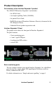
Product Description Full inventory of the Interface Expander 2 product The AP9624 UPS Interface Expander 2 card includes: • the AP9624 card, • two simple signalling Cables (940-0020), • the printed User's Guide, • RoHS (Restriction of Hazardous Substances Directive) document for the EU (European Union), • Schneider Electric product registration card. Interface Expander 2 Panel The graphic below shows the front panel of Interface Expander 2.
Product Description Configuration DIP switches The Interface Expander 2 configuration DIP switches control the shutdown operation of the unit. See “Configuring the Interface Expander 2” on page 11. Status LED The Interface Expander 2 card status LED provides important information concerning operation of the unit. Refer to the table below for a description of the conditions indicated by the LED. Status Description SOLID GREEN Indicates communications and operations are fine.
Key Concepts Simple and smart signalling The communication between an APC by Schneider Electric UPS and a connected server can be of two types: simple signalling or smart signalling. Both simple and smart signalling recognize when a UPS is on battery or when it has a low battery. Smart signalling also continuously monitors the UPS and reports other events in the PowerChute Business Edition software. Master servers and smart signalling.
Key Concepts Configuring PowerChute Business Edition for simple signalling To use PowerChute Business Edition (PowerChute) on a server connected to the Interface Expander 2, configure PowerChute for simple signalling. This procedures pertains to v9.1 and higher of PowerChute. For previous versions, see your PowerChute documentation. 1. Install or re-install PowerChute. 2. When the installation program prompts for the UPS Type, select “Interface Expander Basic Port” and continue with the installation. 3.
Key Concepts Scheduled shutdowns and the Interface Expander 2 When a server that is connected to the computer interface port on the UPS is running software such as PowerChute Business Edition, you can execute scheduled UPS shutdowns for the other servers that are connected to the Interface Expander 2. The Interface Expander 2 recognizes the shutdown signal from the software and signals the On Battery and Low Battery events to attached servers and devices.
Installation Warning: Handle the Interface Expander 2 by the front panel. Do not touch the exposed printed circuit board or components. Touching them might result in damage to the Interface Expander 2. Installation procedure If your UPS configuration uses more than one SmartSlot device, see the online manual addendum called “Installing Multiple Management Cards” on the APC website, available under many SmartSlot accessories including the Interface Expander 2.
Installation 6. Secure the Interface Expander 2 with the screws that you removed at step 3. 7. Proceed with “Connecting to Protected Devices” on page 10.
Connecting to Protected Devices Connection procedure After you have installed the Interface Expander 2 card, you should proceed with connecting the devices to be protected by the card. Refer to the graphic below while performing the following steps. 1. Connect the master server to the smart computer interface port of the UPS. (See “Master servers and smart signalling” on page 5.) Note: A server not supported by PowerChute Business Edition must use simple signalling with the appropriate cable. 2.
Configuring the Interface Expander 2 Shutdown modes Configure the Interface Expander 2 using one of the three available modes of automatic UPS shutdown. (Select a mode using the “DIP Switches” ). • “Confirmed shutdown mode” on page 12 • “Until Low Battery shutdown mode” on page 13 • “Timer shutdown mode” on page 13 After configuration, you should “Test the Interface Expander 2” on page 14. DIP Switches Select the shutdown mode by using the DIP switches as described in the following table.
Configuring the Interface Expander 2 Confirmed shutdown mode In Confirmed mode, the Interface Expander 2 card shuts down the UPS after all connected servers have signalled that they have completed shutdown of the operating system. If any server that is connected to either a) an Interface Expander 2 basic port, or b) the UPS port, is not capable of sending a shutdown confirmation signal, do NOT use Confirmed mode. Behavior of Confirmed mode.
Configuring the Interface Expander 2 Until Low Battery shutdown mode Until Low Battery shutdown mode is similar to the standard operation of the UPS. During an AC utility outage, the Interface Expander 2 card allows the UPS to run on battery until utility power is restored, or until the battery is exhausted. If the Expander 2 card detects a UPS Low Battery condition, it sends a Low Battery signal on all ports for a period of time equal to the Low Battery signal time and then it shuts down the UPS.
Configuring the Interface Expander 2 Test the Interface Expander 2 To check the operation of the Interface Expander 2 card, perform the following steps in the order given. 1. Confirm that the UPS is on and that the battery is fully charged. 2. Verify that the Expander 2 card has been installed, connected, and configured. 3. Confirm that all connected servers and devices are on and running their power management software with power management screens visible, if applicable. 4.
Troubleshooting If you have problems with your Interface Expander 2 card... The troubleshooting chart below covers many of the problems that might arise with the Interface Expander 2 card. If you encounter a problem, refer to this troubleshooting chart first. There may be a simple solution you are overlooking. Problem A server connected to a basic port does not acknowledge On Battery signal. Status LED flashes red continuously. Possible Cause Solution The software screen has not been refreshed.
Troubleshooting Problem One or more servers shuts down when the UPS is on battery, but does not restart when power returns. Possible Cause Solution Timer mode: the operating system shutdown time is too short. The power management software shutdown time, if configured, must be set longer than the Expander 2 card Timer shutdown mode setting. Confirmed mode: the Expander 2 card did not receive shutdown confirmation from servers that shut down, and utility power was restored.
Specifications Basic port pin assignments The following limitations and capabilities apply to the basic ports of the Interface Expander 2: • Pins 3, 5, and 6 are open collector outputs which must be pulled up to a common referenced supply no greater than +40 VDC. • The output at Pin 2 generates a low-to-high RS-232 level when the device is signalling an On Battery condition. The pin is normally at a low RS-232 level.
Specifications Basic port pin assignment graphics The following figures show the DB9 port numbers and the basic port pin assignments.
Specifications Product specifications The following table shows the product specifications for the Interface Expander 2 card. Item Specification Size (H × W × D): 4.0 × 4.0 × 1.5 in (10.2 × 10.2 × 3.8 cm) Weight of the Expander 2 card: 0.2 lb (0.09 kg) Shipping weight: 1 lb (0.
Life-Support Policy General policy Schneider Electric does not recommend the use of any of its products in the following situations: • In life-support applications where failure or malfunction of the Schneider Electric product can be reasonably expected to cause failure of the lifesupport device or to affect significantly its safety or effectiveness. • In direct patient care.
Terms of warranty APC warrants its products to be free from defects in materials and workmanship for a period of two years from the date of purchase. APC will repair or replace defective products covered by this warranty. This warranty does not apply to equipment that has been damaged by accident, negligence or misapplication or has been altered or modified in any way. Repair or replacement of a defective product or part thereof does not extend the original warranty period.
Two-Year Factory Warranty WARRANTIES AND REMEDIES. THE WARRANTIES SET FORTH ABOVE CONSTITUTE APC’S SOLE LIABILITY AND PURCHASER’S EXCLUSIVE REMEDY FOR ANY BREACH OF SUCH WARRANTIES. APC WARRANTIES EXTEND ONLY TO PURCHASER AND ARE NOT EXTENDED TO ANY THIRD PARTIES.
Disclaimer The information presented in this manual is not warranted by Schneider Electric to be authoritative, error free, or complete. Schneider Electric assumes no liability for damages, violations of codes, improper installation, system failures, or any other problems that could arise based on the use of this publication. The information contained in this publication is provided as is. This publication has been compiled in good faith by Schneider Electric.
Interface Expander 2 24
Radio Frequency Interference Changes or modifications to this unit not expressly approved by the party responsible for compliance could void the user’s authority to operate this Warning equipment. USA—FCC This equipment has been tested and found to comply with the limits for a Class A digital device, pursuant to part 15 of the FCC Rules. These limits are designed to provide reasonable protection against harmful interference when the equipment is operated in a commercial environment.
APC Worldwide Customer Care Center Customer support for this or any other product is available at no charge in any of the following ways: • Visit the APC Web site to access documents in the APC Knowledge Base and to submit customer support requests. – www.apc.com (Corporate Headquarters) Connect to localized APC Web sites for specific countries, each of which provides customer support information. – www.apc.com/support/ Global support searching APC Knowledge Base and using e-support.
ユーザーズガイド Interface Expander 2 AP9624
This manual is available in English on the APC Web site (www.apc.com). 本マニュアルの日本語版は APC ウェブサイト (www.apc.
目次 はじめに . . . . . . . . . . . . . . . . . . . . . . . . . . . . . . . . . . . . . . . . . . . . . . 1 概要 ................................................................................. 1 Interface Expander 2 の特長 ........................................... 1 ハードウェアの要件 ........................................................ 2 ケーブルの選択 ............................................................... 2 安全に関する警告 ........................................................... 2 製品の説明 . . . . . . . . . . . . . . . .
目次 タイマーシャットダウンモード .................................... 13 Interface Expander 2 のテスト ...................................... 14 トラブルシューティング . . . . . . . . . . . . . . . . . . . . . . . . . . . . . . . . . 15 Interface Expander 2 カードで問題が生じた場合 ... ..... 15 仕様 . . . . . . . . . . . . . . . . . . . . . . . . . . . . . . . . . . . . . . . . . . . . . . . . . 17 ベーシックポートのピン割り当て ................................ 17 ベーシックポートのピン割り当て図 ............................. 18 製品仕様 ..............................................
はじめに 概要 APC by Schneider Electric ブランドの UPS Interface Expander 2 (AP9624) は、SmartSlot™ アクセサリスロット装備の UPS に 2 つのコンピュータ インターフェイスポートを追加します。 これにより、停電が長引いた場合でも、UPS と電源管理ソフトウェ アは、最大 3 台のネットワークサーバやその他のデバイスを正常にシ ステムシャットダウンすることができます。 Interface Expander 2 の動作に必要な電力は UPS から供給され、UPS に 商用電源から電力が供給されているかどうかにかかわらず、UPS を監 視し、オンバッテリイベントやローバッテリイベントなどの電力状態 をレポートします。 Interface Expander 2 の特長 Interface Expander 2 カード : • SmartSlot アクセサリスロットを装備したサポート対象の APC by Schneider Electric のデバイスに装着可能。 • 異機種混合ネットワークで良好に動作。異なるオペレーティング システムを実行
はじめに ハードウェアの要件 Interface Expander 2 は、SmartSlot を装備し、定格出力が 30kVA 以下の APC by Schneider Electric ブランド UPS デバイスのほとんどのモデルで 使用可能です。 詳細なリストをオンラインで確認するには、http://www.apc.com/site/ support/index.cfm/faq/index.cfm をクリックし、FAQ ID「FA176135」 を検索してください。 ケーブルの選択 次の表に、Interface Expander 2 によってサポートされるシステムで使用 可能なケーブルを表示します。ケーブルを購入する場合には、パーツ 番号を確認してください。 Interface Expander 2 の接続先 Windows サーバ 使用または 発注するケーブル パーツ 番号 940-0020 ケーブル(同梱) UNIX ベーシック UNIX サーバ シグナリングケーブル AP9823 10 または15ft ( 約3 または4.
製品の説明 Interface Expander 2 製品のコンポーネント AP9624 UPS Interface Expander 2 カードには、次のものが同梱されてい ます。 • AP9624 カード • 2 本のシンプルシグナリングケーブル (940-0020) • ユーザーズガイド • EU ( 欧州連合 ) の場合は、RoHS 指令 (Restriction of Hazardous Substances Directive) のドキュメント • シュナイダーエレクトリック製品登録カード Interface Expander 2 のパネル 次の図は、Interface Expander 2 の正面パネルを示しています。 パネルには次のものが含まれます。 • 2 個のベーシックモニタリングポート • 1 個の mini-B タイプ USB ポート • 4 個の設定用 DIP スイッチ • 1 個のステータス LED ベーシックモニタリングポート Interface Expander 2 の 2 個のコンピュータインターフェイスポートは、 UPS 内のオンバッテリおよびローバッテリ状態を検出するシ
製品の説明 設定用 DIP スイッチ Interface Expander 2 の設定用 DIP スイッチは、ユニットのシャットダウ ン動作を制御します。 「Interface Expander 2 の設定」 (11 ページ)を参照 してください。 ステータス LED Interface Expander 2 カードのステータス LED は、ユニットの動作に関 する重要な情報を提供します。LED によって示される状態の説明につ いては、次の表を参照してください。 ステータス 説明 緑の点灯 通信と動作が良好であることを示しています。 緑の点滅 Expander 2 カードが初期化中であることを示 しています。 赤の点滅 Expander 2 カードが UPS との通信を確立で きないか、または通信が持続できないことを 示しています。 UPS が Expander 2 カードによってサポート されていないか、またはこの UPS をサポー トするためにカードのファームウェアを更新 する必要がある可能性があります。 赤の点灯 UPS が Expander 2 カードによってサポート されていない
キーコンセプト シンプルシグナリングおよびスマートシグナリング APC by Schneider Electric ブランドの UPS とサーバ間の通信には、シン プルシグナリングとスマートシグナリングの 2 つのタイプがあります。 シンプルシグナリングとスマートシグナリングはどちらも、UPS がい つオンバッテリであるか、またはいつローバッテリになったかを認識 します。また、スマートシグナリングは継続的に UPS を監視し、 PowerChute Business Edition ソフトウェアにさまざまなイベントをレ ポートします。 マスターサーバおよびスマートシグナリング「マスター」サーバは、 UPS のコンピュータインターフェイスポートに接続されたサーバです。 このサーバは、スマートシグナリング用に設定された PowerChute Business Edition を使用して、UPS を監視および制御します。 すべての UPS デバイスにスマートコンピュータインターフェイスポート が存在するとは限りません (Interface Expander 2 カードが挿入された後 )。 どの UPS デバイスにこ
キーコンセプト PowerChute Business Edition のシンプルシグナリング向けの設定 Interface Expander 2 と接続されたサーバ上で PowerChute Business Edition (PowerChute) を使用するには、PowerChute をシンプルシグナリング用 に設定します。 この手順は v9.1 以上の PowerChute に関係します。それより 前のバージョンの場合は、お手持ちの PowerChute ドキュメ ントを参照してください。 1. PowerChute をインストールまたは再インストールします。 2. インストールプログラムにより UPS タイプの入力が求められた ら、[Interface Expander Basic Port] を選択し、インストールを続行 します。 3. PowerChute を実行し、UPS に接続します。 4.
キーコンセプト スケジュールシャットダウンおよび Interface Expander 2 UPS のコンピュータインターフェイスポートに接続されたサーバが PowerChute Business Edition などのソフトウェアを実行している場合は、 Interface Expander 2 に接続されている他のサーバに対してスケジュール された UPS のシャットダウンを実行できます。 Interface Expander 2 はソフトウェアからのシャットダウン信号を認識 し、接続されたサーバとデバイスにオンバッテリ信号とローバッテリ 信号を送信します。 ベーシックポートに接続されたサーバは、UPS の出力がオフになり、 電力の供給がなくなる前に正常にシャットダウンします。 11 ページの 「シャットダウンモード」を参照してください。 旧世代の UPS デバイスの場合、Interface Expander 2 カードはシャットダウ ンコマンドを受信すると、ローバッテリ期間のあいだ待機してから、シン プルクライアントをシャットダウンするための信号を送信します。その後 シャットダウンコマンドを UPS に
据付 警告:Interface Expander 2 は正面パネルをから操作してください。 覆われていない部分のプリント回路基板やコンポーネントに触 れないでください。触れると Interface Expander 2 に損傷を招く ことがあります。 据付手順 UPS で 1 つ以上の SmartSlot デバイスが使用されている場合は、 Interface Expander 2 を含む SmartSlot アクセサリのオンライン マニュアルの付録「Installing Multiple Management Cards ( 複数 の管理カードをインストールする )」を APC Web サイトから ダウンロードして参照してください。 Interface Expander 2 を据付けるには、次の手順を実行します。 1. 2.
据付 6. Interface Expander 2 を、手順 3 で取り外したネジで固定します。 7.
保護されるデバイスへの接続 接続手順 Interface Expander 2 カードを据付けた後、カードによって保護されるデ バイスと接続してください。 下図を参照しながら、次の手順を実行します。 1. マスターサーバを UPS のスマートコンピュータインターフェイ スポートに接続します(5 ページの「シンプルシグナリングおよ びスマートシグナリング」を参照)。 備考:PowerChute Business Edition がサポートしていないサー バは、対応するケーブルを用いてシンプルシグナリング を使用する必要があります。 2. APC ケーブルを使用して、他の任意のサーバを Interface Expander 2 のベーシックポートに接続します。 備考:Interface Expander 2 のベーシックポートに接続された サーバは、ンプルシグナリングを使用して UPS の監視を 行います (6 ページの「PowerChute Business Edition のシン プルシグナリング向けの設定」を参照 )。 3.
Interface Expander 2 の設定 シャットダウンモード Interface Expander 2 には 3 種類の自動 UPS シャットダウンモードが提 供されています。Interface Expander 2 をいずれかのモードに設定します (「DIP スイッチ」を使用してモードを選択 )。 • 「コンファームシャットダウンモード」(12 ページ ) • 「ローバッテリシャットダウンモード」(13 ページ ) • 「タイマーシャットダウンモード」(13 ページ ) 設定後、 「Interface Expander 2 のテスト」(14 ページ ) を実行する必要が あります。 DIP スイッチ 次の表の説明に従い、DIP スイッチを使用してシャットダウンモード を選択します ( この表の簡略版は Interface Expander 2 の回路基板の底面 にも記載されています )。 シャットダウン モード スイッチの設定 (↓ =0、 ↑ =1) 1 2 3 4 コンファーム 0 0 0 * ローバッテリ 0 0 1 該当 なし 2分 0 1 0 該当
Interface Expander 2 の設定 コンファームシャットダウンモード コンファームモードでは、Interface Expander 2 カードに接続されたすべ てのサーバがオペレーティングシステムのシャットダウンを完了した ことを通知した後に、Interface Expander 2 カードが UPS をシャットダ ウンします。 a) Interface Expander 2 ベーシックポート、または b) UPS ポートのどち らかにシャットダウン確認信号を送信できないサーバが 1 台でも接続 されている場合は、コンファームモードを使用しないでください。 コンファームモードの動作接続されているサーバがオペレーティングシス テムのシャットダウン信号を出す前に電力が回復した場合は、Interface Expander 2 カードはオンラインステータスに戻ります。 Interface Expander 2 は、接続されているすべてのサーバがオペレーティ ングシステムのシャットダウン信号を出す前に、UPS でローバッテリ 状態を検出した場合は、UPS バッテリの残量がゼロになったことを サーバに通
Interface Expander 2 の設定 ローバッテリシャットダウンモード ローバッテリシャットダウンモードは、UPS の標準動作と同様です。 AC 電源が停電の間、Interface Expander 2 カーは、AC 電源の電力が回 復するか、バッテリ残量がゼロになるまで UPS をオンバッテリで稼働 させます。 Interface Expander 2 カードは UPS ローバッテリ状態を検出すると、 ローバッテリ信号時間と等しい期間、すべてのポートでローバッテリ信 号を送信してから、UPS をシャットダウンします。 ローバッテリタイマーの始動後に、AC 電源の電力が回復した場合、 Interface Expander 2 カードはカウントダウンを続行し、強制的に UPS の電源を入れ直します。 このモードは、最大限の実行時間が必要なアプリケーションで役立ち ます。 タイマーシャットダウンモード タイマーシャットダウンモードでは、Interface Expander 2 カードは、 ユーザが指定した期間 UPS をオンバッテリで稼働させてから、UPS を シャットダウンします。有効なタイマーの
Interface Expander 2 の設定 Interface Expander 2 のテスト Interface Expander 2 カードの動作を確認するには、次の手順を順番通り に実行します。 1. UPS がオンでバッテリがフル充電されていることを確認します。 2. Interface Expander 2 カードが据付、接続、および設定されている ことを確認します。 3. 接続されているすべてのサーバとデバイスがオンになっていて、 電力管理ソフトウェアが ( 可能な場合は表示可能な電力管理画面 で ) 稼働していることを確認します。 4. Interface Expander 2 カードのステータス LED がオンで、通常動作 を示していることを確認します。 5. AC 電源に電力障害が発生している状態を疑似的に再現させます。 6.
トラブルシューティング Interface Expander 2 カードで問題が生じた場合 ...
トラブルシューティング 問題 原因 タイマーモード:オペ レーティングシステムの シャットダウン時間が短 すぎる。 UPS がオンバッテリの ときに 1 台以上のサー バがシャットダウンす るが、電力の回復時に 再起動しない。 コンファームモード : Interface Expander 2 カード がシャットダウンする サーバからシャットダウ ン確認を受信せず、AC 電 源の電力が復元された。 サーバはシャットダウン したが、UPS がシャット ダウンしていない。 UPS ポートに接続さ れているサーバが UPS と通信できない。 対処方法 設定されている場合は、 電力管理ソフトウエア のシャットダウン時間 が、Interface Expander 2 カードのタイマーシャッ トダウンモードの設定よ り長く設定されている必 要があります。 サーバがシャットダウ ンを確認できることを 検証してください。 確認できない場合は、 Interface Expander 2 カー ドをタイマーシャット ダウモードまたはロー バッテリシャットダウ ンモードに設定してく ださい。 通信のケーブルが適切に
仕様 ベーシックポートのピン割り当て Interface Expander 2 のベーシックポートには、次の制限と機能が適用さ れます。 • ピン 3、5、および 6 は、オープンコレクタ出力で、+40 VDC 未 満の共通基準電源まで引き上げる必要があります。 • ピン 2 の出力は、デバイスがオンバッテリ状態を通知するときに Low-to-High RS-232 レベルを生成します。 ピンは通常、Low RS-232 レベルです。 • Interface Expander 2 ユニットは、High RS-232 レベルを 4.
仕様 ベーシックポートのピン割り当て図 以下の図は、DB9 ポート番号とベーシックポートのピン割り当てを示 しています。 ㅢᏱࠝࡊࡦ ࿁✢㓚ኂାภ ㅢᏱࠝࡊࡦ ࡠࡃ࠶࠹ାภ ㅢᏱࠢࡠ࠭ ࿁✢㓚ኂାภ ࠦࡕࡦ UPS ࠪࡖ࠶࠻࠳࠙ࡦ RS-232 ജ ࿁✢㓚ኂ RS-232 ജ ࠪࡖࠪ ?2: ?????????? 18 Interface Expander 2
仕様 製品仕様 次の表は、Interface Expander 2 カードの製品仕様を示しています。 項目 仕様 寸法・質量 10.2 × 10.2 × 3.8 cm (4.0 × 4.0 × 1.5 in) 寸法(H × W × D): Interface Expander 2 カードの 重量 : 0.09 kg(0.2 lb) 積荷重量 : 0.
安全性 一般情報 Schneider Electric は、次の状況においてこの製品のご利用をお勧めして おりません。 • Schneider Electric 製品の障害または機能不全が、生命維持装置の 障害を招くと予測される状況、あるいはこれらの装置の安全性や 効果に大きな影響を与えると予測される状況。 • 直接的な患者治療。 (a) 怪我や損傷の危険性が最低限に抑えられていること、(b) リスクのす べてをお客様が負うこと、そして (c) この状況下における Schneider Electric の責任が十分に保護されていることが、書面ならびに Schneider Electric に納得できる形で報告されていない限り、この用途の使用に対 して Schneider Electric が故意に製品を販売することはありません。 生命維持装置の例 生命維持装置 と言う用語は新生児用酸素濃度計、神経刺激装置 ( 麻酔、 鎮痛、および他の用途も含む )、輸血装置、血液ポンプ、心臓細動除去 器、不整脈検出および警報装置、ペースメーカー、血液透析システム、 腹膜透析システム、新生児保育器、人工呼吸器 ( 成人用およ
保証の条件 APC は、お客様のご購入日から 2 年間、製品に原材料や作業工程の欠 陥が無い事を保証します。APC は本保証の対象製品の欠陥を修理また は交換するものとします。その他の損害、例えば事故、過失、操作誤 り、または製品の改竄等による損傷に対しては、この保証は一切適用さ れません。本項に記載の欠陥製品または部品の修理や交換により元の保 証期間が延長されることはありません。本保証下で供給される部品は、 新品または工場で再製造されたものである場合があります。 第一購入者の保証 本保証は製品のユーザ登録を行った当初購入者にのみ適用されます。 本製品の登録は、APC の Web サイト (www.apc.
2 年間の工場保証 いかなる場合も、製品の使用、サービス、または設置から生じた いかなる間接的、特別、結果的、懲罰的損害についても、その損 害が契約の記述または不法行為の有る無しを問わず、過失または 怠慢、厳格責任に関係なく、APC が事前にそのような損害の可 能性を通知したかどうかに関わらず、APC、同社幹部、取締役、 支社、従業員はその責任を負わないものとします。特に、利益損 失、収入損失、機器の損失、機器の使用機会の損失、ソフトウェ アの損失、データの損失、交換の代価、第三者による代価要求な どのあらゆる代価に対して APC は責任を負わないものとします。 APC の販売担当者、従業員、または販売代理店は、本保証の条 項を追加または変更する権限はありません。保証の条件は、たと え変更される場合も、APC の役員と法務部の署名により書面に よってのみ変更可能です。 保証の請求 保証の請求に際しては、APC の Web サイトの「サポート」ページ (www.apc.
免責条項 本書に掲載の情報は、Schneider Electric が、信頼でき、誤りがなく、 完全であることと保証するものではありません。従って、Schneider Electric は、本書の使用に基づいて発生する可能性がある損傷、法規違 反、据付の誤り、システムの不具合またはその他の問題に対する責任を 負わないものとします。 本書に含まれる情報は「現状通り」で提供されています。本書は Schneider Electric により作成されています。本書に含まれる情報の完全 性または正確性に関して、明示または黙示に関わらず表明するものでも 保証するものでもありません。 Schneider Electric、または Schneider Electric の系列会社、子会社、 あるいはこれらの会社の支店、取締役、従業員はいかなる場合も、 Schneider Electric がそれらの損害の危険性を明確に助言した場合でも、 本書またはその内容の使用または非使用に関連した、またはその結果生 起した取引、契約、収入、データ、情報の損失または事業の中断を含む がこれに限定されないあらゆる直接、間接、必然的、懲罰的、特
Radio Frequency Interference Changes or modifications to this unit not expressly approved by the party responsible for compliance could void the user’s authority to operate this Warning equipment. USA—FCC This equipment has been tested and found to comply with the limits for a Class A digital device, pursuant to part 15 of the FCC Rules. These limits are designed to provide reasonable protection against harmful interference when the equipment is operated in a commercial environment.
APC Worldwide カスタマケアセンター 本製品および他の製品に関するカスタマサポートは、以下の方法で無償で提供 されています。 • APC の Web サイトを閲覧すると、APC Knowledge Base 内の資料を参照 したり、お客様のご要望を送信することができます。 – www.apc.com(本社) 特定の国の、ローカライズした APC の Web サイトにアクセスします。 それぞれのページにカスタマサポート情報があります。 – www.apc.com/support/ APC Knowledge Base 内での検索および e-support を行えるグローバル サポートがあります。 • APC カスタマサポートには電話または E-mail で問い合わせることもで きます。 – 地域、国別のセンター:お問い合わせ先については、 www.apc.com/support/contact を参照してください。 お住まいの地域のカスタマサポートについては、製品を購入された営業担当ま たは販売店にお問い合わせください。 © 2013 APC by Schneider Electric.