
Specifications


Advanced Configuration Features
31004624 8/2009 109
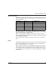
Each block has a fixed number of registers reserved for its use. Whether or not all
the registers reserved for that block are used in an application, the number of
registers allocated to that block remains constant. This permits you to know at all
times where to begin looking for the type of data of interest to you.
For example, to monitor the status of the I/O modules in the process image, look at
the data in block 11 beginning at register 45392.
Reading Register Data
All the registers in the data image can be read by an HMI panel connected to the
island at the NIM’s CFG port (see page 32). The Advantys configuration software
reads all this data, and displays blocks 1, 2, 5, 8, 10, 11, and 12 in the Modbus Image
screen in its I/O Image Overview.
Writing Register Data
Some registers, usually configured number of registers in block 12 (registers
49488 through 49999) of the data image, may be written to by an HMI panel
(see page 128).
The Advantys configuration software or an HMI panel may also be used to write data
to the registers in block 1 (registers 40001 through 44096). The configuration
software or the HMI panel must be the island bus master in order for it to write to the
data image—i.e., the island must be in test mode.