
Specifications


Advanced Configuration Features
31004624 8/2009 123
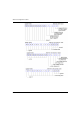
The Input Data and I/O Status Process Image
Now let’s look at the register allocation required to support the input data and I/O
status process image (see page 111). This is the information that the NIM collects
from the island modules so that it can be read by the fieldbus master or by some
other monitoring device.
All eight I/O modules are represented in this process image block. The modules are
assigned registers in the order of their island bus addresses, starting at
register 45392.
Each digital I/O module uses two contiguous registers:
z Digital input modules use one register to report data and the next to report status.
z Digital output modules use one register to echo output data and the next to report
status.
NOTE: The value in an echo output data register is basically a copy of the value
written to the corresponding register in the output data process image. Generally,
this is the value written to the NIM by the fieldbus master, and its echo is of not much
interest. When an output channel is configured to perform a reflex action
(see page 99), however, the echo register provides a location where the fieldbus
master can look to see the current value of the output.
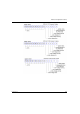
The analog input module uses four contiguous registers:
z the first register to report the data for channel 1
z the second register to report status for channel 1
z the third register to report the data for channel 2
z the fourth register to report status for channel 2
The analog output module uses two contiguous registers:
z the first register to report status for channel 1
z the second register to report status for channel 2