
Server User Manual


63230-216-207/A3 Appendix C—Using a Crossover Cable to Configure the Power Server
9/2002
37
© 2002 Schneider Electric All Rights Reserved
14. After you have connected to the Power Server via NetMeeting, press
Ctrl-W on your keyboard to switch to the Power Server desktop.
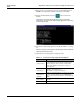
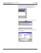
15. Double click the Network Setup icon on the Power Server
desktop.
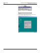
NOTE: Even if the Power Server will not be used in a networked
environment, you must run the Network Setup application at least once
and then type 5 to quit.
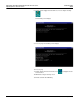
16. Set all of the network setup options as described in Table C–1 on page
37.
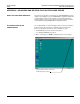
NOTE: To change any of the options, type the option number at the Enter
Option prompt and press Enter.
17. Follow the onscreen instructions to change the value.
Table C–1: Power Server Setup—HyperTerminal Options
Option Description
Computer Name
The computer name defaults to the MAC Address. We
recommend that you leave the default computer name. If
you must change the name, it must be a unique alpha-
numeric name, limited to 15 characters, no spaces or
special characters.
IP Address 1
Subnet Mask 1
Use IP Address 1 as the primary address to access all the
capabilities of the Power Server.
Subnet Mask 1 is assigned to IP Address 1.
IP Address 2
Subnet Mask 2
(optional)
IP Address 2 and Subnet Mask 2 are optional. They should
only be used if slave Modbus/Jbus and POWERLOGIC
devices need to have the same address on both COM 3 and
COM 4.
Router Address
Address of your company’s Ethernet LAN router, if
applicable.
MAC Address Unique media access control number (cannot be changed).