Instruction Bulletin 63230-216-207/A3 9/2002 Replaces 63230-216-207/A2 dated January 2002 POWERLOGIC® Power Server PWRSRV710 and PWRSRV750 Models Setup Guide Retain for future use.
NOTICE Read these instructions carefully and look at the equipment to become familiar with the device before trying to install, operate, or maintain it. The following special messages may appear throughout this bulletin or on the equipment to warn of potential hazards or to call attention to information that clarifies or simplifies a procedure.
63230-216-207/A3 9/2002 CONTENTS Contents CHAPTER 1—INTRODUCTION . . . . . . . . . . . . . . . . . . . . . . . . . . . . . . . . 1 Overview . . . . . . . . . . . . . . . . . . . . . . . . . . . . . . . . . . . . . . . . . . . . . . . . . . . 1 CHAPTER 2—SAFETY PRECAUTIONS . . . . . . . . . . . . . . . . . . . . . . . . . . 3 CHAPTER 3—INSTALLATION . . . . . . . . . . . . . . . . . . . . . . . . . . . . . . . . . 5 Dimensions . . . . . . . . . . . . . . . . . . . . . . . . . . . . . . . . . . . . . . . .
Contents 63230-216-207/A3 9/2002 APPENDIX F—CONNECTING THIRD PARTY DEVICES TO THE POWER SERVER . . . . . . . . . . . . . . . . . . . . . . . . . . . . . . . . . . . . . . . . . . . 47 APPENDIX G—POWERLOGIC SYSTEM DISPLAY (SD700) INSTALLATION . . . . . . . . . . . . . . . . . . . . . . . . . . . . . . . . . . . . . . . . . . . . 53 Product Description . . . . . . . . . . . . . . . . . . . . . . . . . . . . . . . . . . . . . . . . . . 53 Installation and Operation . . . . . . . . . . . . . . . . . . . . . .
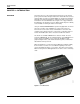
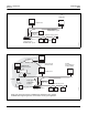
63230-216-207/A3 9/2002 Chapter 1—Introduction Overview CHAPTER 1—INTRODUCTION OVERVIEW The Power Server is a self-contained device that can be used to transfer power system information through a web browser and an Ethernet local area network (LAN) or a wide area network (WAN). It is designed specifically for industrial and commercial applications, making it possible to view system information from a standard web browser. Figure 1–2 on page 2 illustrates this application.
Chapter 1—Introduction Overview 63230-216-207/A3 9/2002 Initial setup via NetMeeting Web browser Device setup for the POWERLOGIC System Optional touch screen Mixed-mode daisy chain 30703059 Power Server used as a component of the POWERLOGIC System Figure 1–2: The Power Server used as a standalone system monitoring device POWERLOGIC Enterprise System Internet View reports via Internet browser POWERLOGIC Enterprise System PC with System Manager Software (SMS) Internet Web browser Firewall via Eth
63230-216-207/A3 9/2002 CHAPTER 2—SAFETY PRECAUTIONS Chapter 2—Safety Precautions DANGER HAZARD OF ELECTRIC SHOCK, BURN, OR EXPLOSION • Only qualified workers should install this equipment. Such work should be performed only after reading this entire set of instructions. • NEVER work alone. • Turn off all power supplying this equipment before working on or inside. • Always use a properly rated voltage sensing device to confirm that all power is off.
Chapter 2—Safety Precautions 4 63230-216-207/A3 9/2002 © 2002 Schneider Electric All Rights Reserved
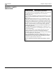
63230-216-207/A3 9/2002 Chapter 3—Installation Dimensions CHAPTER 3—INSTALLATION DIMENSIONS 5.63 in 143 mm 8.98 in 228 mm 3.62 in 30703001 92 mm Figure 3–1: Power Server dimensional drawing MOUNTING The Power Server is designed to be mounted directly on a 1.38 in (35 mm) DIN rail. The unit has a snap-on DIN rail connector on the back (see Figure 3–2). No tools are required. Mount the Power Server in a clean, dry, well ventilated area. Allow 15.
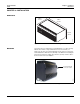
Chapter 3—Installation Mounting 63230-216-207/A3 9/2002 30703003 Mount the Power Server and Power Supply only in a horizontal position as shown in Figure 3–3. Figure 3–3: Proper orientation of Power Server and power supply DANGER HAZARD OF ELECTRIC SHOCK, BURN, OR EXPLOSION • Turn off all power supplying this equipment and the equipment in which it is installed before working on this equipment. • Always use a properly rated voltage sensing device to confirm that power is off.
63230-216-207/A3 9/2002 Chapter 3—Installation Mounting To mount the Power Supply (Square D part no. PS080), refer to Figure 3–4 and follow these steps: 1. Align the mounting groove on the power supply with the DIN rail. 2. Press the blue button to pull back the tabs. 3. Snap the power supply onto the DIN rail and release the blue button to secure the unit onto the DIN rail. 30703004 30703005 NOTE: Refer to Appendix A—Specifications on page 29 for PS080 specifications.
Chapter 3—Installation Mounting 8 63230-216-207/A3 9/2002 © 2002 Schneider Electric All Rights Reserved
63230-216-207/A3 9/2002 Chapter 4—Connections Connections Summary CHAPTER 4—CONNECTIONS CONNECTIONS SUMMARY The Power Server connections are described in this chapter. Table 4–1 briefly describes each connection. Table 4–1: Connections description Connection Description UTP Port Ethernet connection. Standard RJ-45 port for connection of unshielded twisted-pair (10/100 BaseT) Ethernet cable. Category 5 recommended. Control Power Three-pin connector for 24 Vdc connection.
Chapter 4—Connections Control Power CONTROL POWER 63230-216-207/A3 9/2002 The Power Server accepts 24 Vdc control power with maximum power consumption of 28 watts. A 50-watt power supply is recommended for this application (order Square D part no. PS080). NOTE: Check for proper polarity before applying power to the unit. Fusing We recommend using one 2 A fast-blow fuse as shown in Figure 4–2 and Figure 4–3 on page 11.
63230-216-207/A3 9/2002 Chapter 4—Connections Control Power Power Server + – 2 A Fast-Blow Fuse recommended To local equipment ground 24 Vdc – + L N 100–240 Vac Source 30703010 Power Supply (PS080) Figure 4–3: Power Server grounding to local equipment © 2002 Schneider Electric All Rights Reserved 11
Chapter 4—Connections RS-232 Serial Ports The Power Server has two RS-232 serial communications ports. 30703006 RS-232 SERIAL PORTS 63230-216-207/A3 9/2002 COM 1 COM 2 Figure 4–4: COM 1 and COM 2 ports COM 1 COM 1 is the port used for configuring the Power Server. When you attach a laptop or PC to this port, you can follow the instructions in this bulletin to configure the network settings of the Power Server.
63230-216-207/A3 9/2002 RS-485 PORTS Chapter 4—Connections RS-485 Ports Table 4–2 shows the default values for each of the RS-485 ports. Table 4–2: Default Values for RS-485 Ports Value Default Setting COM 3 and COM 4 Type 4-wire Baud Rate Speed 19200 Parity Even NOTE: On a 4-wire mixed mode (POWERLOGIC and Modbus) daisychain, device address 1 cannot be a POWERLOGIC or SY/MAX device and device address 16 cannot be a Modbus device.
Chapter 4—Connections Connecting 4-Wire Devices as 2-Wire 63230-216-207/A3 9/2002 Biasing and Termination Each RS-485 port has built-in communications signal biasing and termination circuitry. Thus, a multipoint communications adapter is not needed. However, an end-of-line terminator (Square D part no. MCT-485 or MCTAS-485) is required on the last device of each daisy chain. Refer to the instruction bulletin for the last device on the daisy chain.
63230-216-207/A3 9/2002 COMMUNICATIONS WIRING Chapter 4—Connections Communications Wiring The maximum number of devices supported on a single daisy chain is determined based on baud rate, the length of the daisy chain, and the types of RS-485 devices (2-wire/4-wire) on the daisy chain. The RS-485 interface supports daisy chains as specified in Table 4–3 and Table 4–4.
Chapter 4—Connections Communications Wiring 16 63230-216-207/A3 9/2002 © 2002 Schneider Electric All Rights Reserved
63230-216-207/A3 9/2002 Chapter 5—Setup Summary of Setup Steps CHAPTER 5—SETUP SUMMARY OF SETUP STEPS This chapter describes the steps for setting up the Power Server. To do this, you perform these main tasks: 1. Configure the Power Server communication connection using your laptop or PC. 2. Configure the PowerLogic System application using NetMeeting.
Chapter 5—Setup Configuring the Power Server Communication Connection 63230-216-207/A3 9/2002 4. Enter a name for your setup connection and select OK. 5. Define your connection. From the dropdown menu, select the COM port on the PC that you are using to connect to the Power Server. 30703013 6. Click OK. The COM port Properties dialog displays. 7. Set the serial port settings as shown above and click OK when finished. The HyperTerminal entry screen displays. Enter: Pwr_Srv 8.
63230-216-207/A3 9/2002 Chapter 5—Setup Configuring the Power Server Communication Connection 30703014 9. At the C:\ > prompt, enter: nwsetup The PowerLogic Network Setup Application displays in HyperTerminal. NOTE: Even if the Power Server will not be used in a networked environment, you must run the Network Setup application at least once and then type 5 to quit. 10. Set all of the network setup options as described in Table 1.
Chapter 5—Setup Connecting to the Power Server with NetMeeting 63230-216-207/A3 9/2002 Now you are ready to configure the POWERLOGIC System applications as described in the next section, Connecting to the Power Server with NetMeeting. CONNECTING TO THE POWER SERVER WITH NETMEETING To perform this procedure, you can either connect remotely from a networked PC as illustrated in Figure 5–2, or you can connect directly from your PC to the Power Server using a crossover cable (not supplied).
63230-216-207/A3 9/2002 Starting NetMeeting Chapter 5—Setup Connecting to the Power Server with NetMeeting 1. From your PC, launch NetMeeting. Click Start > Programs > Accessories > Communications > Netmeeting (Windows 2000 path). 30703016 2. To connect to the Power Server using Netmeeting, click Tools > Options > Security and check “I prefer to make secure outgoing calls” and click OK. You should only have to do this once. NetMeeting stores this preference.
Chapter 5—Setup Connecting to the Power Server with NetMeeting 63230-216-207/A3 9/2002 30703018 3. Call the Power Server. Enter the IP address in NetMeeting and click the “Place a Call” button. Use IP address 1 that you entered in nwsetup on page 19. The Remote Desktop Sharing dialog displays. 4. For User, enter: PowerServerAdmin For Password (case-sensitive), enter: Pwr_Srv Leave domain blank and click OK.
63230-216-207/A3 9/2002 CONFIGURING THE POWER SERVER Chapter 5—Setup Configuring the Power Server 1. Use NetMeeting to access the Power Server. The Power Server splash screen displays. NOTE: During the startup process, the Power Server displays the splash screen with a DO NOT TOUCH Ø symbol. Wait until this symbol no longer displays before proceeding with the configuration.
Chapter 5—Setup Configuring the Power Server 63230-216-207/A3 9/2002 2. Press Ctrl-W to display the Power Server desktop. The Power Server desktop displays. Verify that all the taskbar icons display as shown in Figure 5–3. Power Server icon Powerlogic Server icon Taskbar icons NOTE: Icons may be arranged differently than they are shown in this illustration. Figure 5–3: Power Server Desktop To configure the Power Server you: 1. Set the time zone and daylight savings time preference. 2.
63230-216-207/A3 9/2002 Chapter 5—Setup Configuring the Power Server Setting the Date/Time and Time Zone To update the date/time and time zone settings follow these steps: 1. In the taskbar, double click the time display. The Date/Time Properties dialog displays. 30703022 2. Click the Time Zone tab to display it. 3. Select your time zone from the pull down list, select your preference for daylight savings, and click Apply. 30703021 4. Click the Date & Time tab to display it.
Chapter 5—Setup Configuring the Power Server 63230-216-207/A3 9/2002 5. Set the new date and time, then click Apply. 6. Click OK to exit and save the changes. 7. Set the Power Server to setup mode as described in the following section, Changing the Mode from Run to Setup Mode.
63230-216-207/A3 9/2002 Configuring Your POWERLOGIC System Chapter 5—Setup Configuring the Power Server While in setup mode, you can add devices to the POWERLOGIC System. Serial connections for COM 3 and COM 4 of the Power Server are already defined in the system. Do not delete these settings or define a new communication connection for COM 3 or COM 4 ports. To add devices to the Power Server, follow these steps. 1. Double click the PowerLogic Server icon the application. on the desktop to launch 2.
Chapter 5—Setup Configuring the Power Server Changing the Mode from Setup to Run Mode 63230-216-207/A3 9/2002 To change from setup mode to run mode, do the following: 1. Return the Power Server back to run mode: click the red Power Server icon on the taskbar at the bottom right-hand portion of the screen. The Embedded Switch dialog displays. 2. Click the Run Mode button. The Power Server will reboot in run mode for normal operations.
63230-216-207/A3 9/2002 Appendix A—Specifications APPENDIX A—SPECIFICATIONS Table A–1: Power Server Specifications Type Description CONTROL POWER INPUT SPECIFICATIONS Operating Input Range 24 Vdc (± 10%) [sourced by Class 2 rated supply] Burden, max. 28 W ENVIRONMENTAL Ambient Operating Temperature 0 to 50°C (< 95% relative humidity, noncondensing) Ambient Storage Temperature –20°C to 70°C Sealing IP30: Sealed against particles > 2.5 mm Altitude (maximum) 15,000 ft. (4.
Appendix A—Specifications 30 63230-216-207/A3 9/2002 © 2002 Schneider Electric All Rights Reserved
63230-216-207/A3 9/2002 Appendix B—Changing Your Password APPENDIX B—CHANGING YOUR PASSWORD We recommend that you change your password after completing setup of the Power Server. To do this, follow these steps: 1. From the taskbar of your laptop or PC, launch NetMeeting and connect to the Power Server. See “Starting NetMeeting” on page 21 for instructions. If the Power Server is up and running, press Ctrl-W on your keyboard to switch to the Power Server desktop 2. Place the Power Server in setup mode.
Appendix B—Changing Your Password 63230-216-207/A3 9/2002 30703050 7. Double click the Power Server administrator line for the name created in the previous step. The User Properties dialog displays. 8. Type the new password in the Password and Confirm Password boxes and click OK. 9. Close the User Manager. 10. Return the Power Server to run mode. See “Changing the Mode from Setup to Run Mode” on page 28 for instructions. The new password will take effect immediately.
63230-216-207/A3 9/2002 Appendix C—Using a Crossover Cable to Configure the Power Server APPENDIX C—USING A CROSSOVER CABLE TO CONFIGURE THE POWER SERVER If you choose to use a cross-over cable to configure the Power Server, follow these steps: Cross-over cable Ethernet UTP port 30703012 30703006 1. Connect the cross-over cable from the Ethernet UTP port on the Power Server to your PC as illustrated in Figure C–1. Figure C–1: Cross-over connection for Power Server configuration 2.
Appendix C—Using a Crossover Cable to Configure the Power Server 63230-216-207/A3 9/2002 5. From the Local Area Connection Status dialog box, click Properties. The Local Area Connection Properties dialog box displays. 6. From the Local Area Connection Properties dialog box, select Internet Protocol (TCP/IP) and click Properties. The Internet Protocol (TCP/IP) Properties dialog box displays. 7. From the Internet Protocol (TCP/IP) Properties dialog box, select “Use the following IP address.” 8.
63230-216-207/A3 9/2002 Appendix C—Using a Crossover Cable to Configure the Power Server 30703016 11. To connect to the Power Server using Netmeeting, click Tools > Options > Security and check “I prefer to make secure outgoing calls.” You should only have to do this once. NetMeeting stores this preference. Netmeeting displays the Not in a Call dialog.
Appendix C—Using a Crossover Cable to Configure the Power Server 63230-216-207/A3 9/2002 30703057 12. Call the Power Server. Enter the IP address in NetMeeting and click the “Place a Call” button. For this initial configuration, use IP address: 10.10.10.10 30703018 The Remote Desktop Sharing dialog displays. 13. For User, enter: PowerServerAdmin For Password (case-sensitive), enter: Pwr_Srv Leave domain blank.
63230-216-207/A3 9/2002 Appendix C—Using a Crossover Cable to Configure the Power Server 14. After you have connected to the Power Server via NetMeeting, press Ctrl-W on your keyboard to switch to the Power Server desktop. 15. Double click the Network Setup icon desktop. on the Power Server NOTE: Even if the Power Server will not be used in a networked environment, you must run the Network Setup application at least once and then type 5 to quit. 16.
Appendix C—Using a Crossover Cable to Configure the Power Server 63230-216-207/A3 9/2002 18. After changing the options, verify that all settings are correct. 19. At the Enter Option prompt, type 5 to quit. The Power Server reboots automatically. During the reboot, your NetMeeting session is closed automatically. Now you are ready to configure the PowerLogic System applications as described in the section, “Connecting to the Power Server with NetMeeting” on page 20.
63230-216-207/A3 9/2002 Appendix D—Integrating the Power Server into SMS APPENDIX D—INTEGRATING THE POWER SERVER INTO SMS This appendix provides instructions for using System Manager Software (SMS) to set up a PC interface to communicate through the Power Server as a gateway to the Power Server’s attached serial slave devices. To communicate with SMS through the Power Server, follow these steps: 1. Launch SMS. 2. Open an existing system or create a new system. 3. Add a communication connection.
Appendix D—Integrating the Power Server into SMS 40 63230-216-207/A3 9/2002 © 2002 Schneider Electric All Rights Reserved
63230-216-207/A3 9/2002 Appendix E—Uploading And Deleting Files On the Power Server About the Software Warranty APPENDIX E—UPLOADING AND DELETING FILES ON THE POWER SERVER ABOUT THE SOFTWARE WARRANTY The Power Server products are intended for use with POWERLOGIC System software only. Installation of any non-POWERLOGIC compatible software will void the warranty for this product.
Appendix E—Uploading And Deleting Files On the Power Server Uploading Files to the Power Server 63230-216-207/A3 9/2002 3. Click the Minimize button in the top right corner to minimize the NetMeeting Target’s desktop. Click OK if “Meeting Properties” or “The directory server could not be found” dialogs display. Then, click the Transfer Files icon on the NetMeeting connection dialog. 4. Wait for the Add Files icon to become enabled, then click it. 5.
63230-216-207/A3 9/2002 Appendix E—Uploading And Deleting Files On the Power Server Uploading Files to the Power Server 6. Click the Send All icon. 7. Restore the Target’s desktop window and then close all the Transfer complete dialogs that displayed during the transfer.
Appendix E—Uploading And Deleting Files On the Power Server Uploading Files to the Power Server 63230-216-207/A3 9/2002 8. Double click the Apply Transferred Files icon on the Target’s desktop. The following screen displays. 9. Press any key. The following screen displays. 10. Press any key. 11. Double-click the Power Server browser icon Server browser. to display the Power 12. Minimize the Target’s desktop screen. 13. End the call and exit NetMeeting.
63230-216-207/A3 9/2002 DELETING FILES ON THE POWER SERVER Appendix E—Uploading And Deleting Files On the Power Server Deleting Files on the Power Server To delete uploaded files, do the following: 1. Start NetMeeting and connect to the Power Server. See “Starting NetMeeting” on page 21. 2. Once connected, press Ctrl-W to display the Power Server desktop. 3. Open the Access Transferred Files folder by double clicking the desktop icon. 4. Select files to be deleted. 5. Click File > Delete. 6.
Appendix E—Uploading And Deleting Files On the Power Server Deleting Files on the Power Server 46 63230-216-207/A3 9/2002 © 2002 Schneider Electric All Rights Reserved
63230-216-207/A3 9/2002 Appendix F—Connecting Third Party Devices to the Power Server APPENDIX F—CONNECTING THIRD PARTY DEVICES TO THE POWER SERVER You can connect third party devices to the Power Server using a custom install application. Contact your field sales representative to determine the availability of the custom install application for a particular device. If you have retained the custom files, follow these steps to install the files and connect to the device. 1. Start NetMeeting.
Appendix F—Connecting Third Party Devices to the Power Server 63230-216-207/A3 9/2002 5. Click the Transfer Files icon. 6. Click Add Files. 7. Select all the files for the custom install application and click Add.
63230-216-207/A3 9/2002 Appendix F—Connecting Third Party Devices to the Power Server 8. Click Send All. 9. When all files have transferred, close the File Transfer dialog. 10. Click the “Target’s Desktop” window.
Appendix F—Connecting Third Party Devices to the Power Server 63230-216-207/A3 9/2002 11. Click the Power Server icon on the bottom right of your taskbar. Power Server icon The Power Server Embedded Switch dialog displays. 12. Click the Setup Mode button to change to setup mode. After changing to setup mode, your NetMeeting session will be disconnected while the Power Server restarts automatically. This process may take up to two minutes. 13. Reconnect to the Power Server with NetMeeting. 14.
63230-216-207/A3 9/2002 Appendix F—Connecting Third Party Devices to the Power Server 15. Double-click the My Computer icon on the Power Server desktop and open the C:\Netmeeting Received Files folder. 16. Double-click Setup.exe. 17. Follow the onscreen instructions in the wizard.
Appendix F—Connecting Third Party Devices to the Power Server 63230-216-207/A3 9/2002 18. Upon completion of the install wizard, select “No. I will start my computer later.” 19. Click Finish. 20. Select all the files in the “C:\NetMeeting Received Files” folder and delete them. 21. Close the My Computer window. 22. Delete the files in your recycle bin by right-clicking the desktop icon and selecting “Empty Recycle Bin.
63230-216-207/A3 9/2002 Appendix G—POWERLOGIC System Display (SD700) Installation Product Description APPENDIX G—POWERLOGIC SYSTEM DISPLAY (SD700) INSTALLATION PRODUCT DESCRIPTION The System Display is a full-color, panel-mount touch screen display designed to be mounted on power equipment. The system display lets you view the Power Server screens locally at the equipment.
Appendix G—POWERLOGIC System Display (SD700) Installation Calibrating the Touch Screen 63230-216-207/A3 9/2002 3. Connect the female end of the serial cable to the COM 2 serial port on the Power Server (see Figure G–2). Tighten the captive screws on the cable connector. 4. Connect the male end of the serial cable to the Touch Screen Serial Output port on the system display. Tighten the captive screws on the cable connector. 5. Locate the video cable supplied with the system display. 6.
63230-216-207/A3 9/2002 Appendix G—POWERLOGIC System Display (SD700) Installation Specifications SPECIFICATIONS Table G–1: Specifications Display Type Active matrix color thin film transistor (TFT) LCD Nominal Display Area Diagonal 12.1 in (308 mm) Resolution 800 x 600 pixels Electrical Input voltage 100-240 Vac, 50–70 Hz, 0.5 A SD700 DC option: 24 Vdc (± 10%) [sourced by Class 2 rated supply], 1.
Appendix G—POWERLOGIC System Display (SD700) Installation Specifications 56 63230-216-207/A3 9/2002 © 2002 Schneider Electric All Rights Reserved
63230-216-207/A3 9/2002 Appendix H—Database Backup Backing Up the Database on the Power Server APPENDIX H—DATABASE BACKUP The Power Server contains four SQL databases: master, msdb, SMS-System and SMS-History. By default, the Power Server automatically backs up these databases every month. Although the master and msdb databases are SQL system databases and they do not get updated frequently, the System and History databases hold all the Power Server configuration and data.
Appendix H—Database Backup Backing Up the Database on the Power Server 63230-216-207/A3 9/2002 The web page displays “Job command sent” and the Power Server starts backing up the database on the Power Server. Checking the Database Backup Status To check the status of the database backup, follow these steps: 1. Type http://Power Server IP/ to browse the main Power Server user interface (using the IP address of the Power Server for “Power Server IP”). 2. Click the Maintenance tab.
230-216-207/A3 9/2002 BACKING UP THE POWER SERVER DATABASE ONTO A SEPARATE PC Appendix H—Database Backup Backing Up the Power Server Database onto a Separate PC In addition to backing up the database on the Power Server, we recommend saving your backups onto a separate PC on a regular basis. To do so, follow these steps: 1. Type ftp://Power Server IP/SQL in Internet Explorer using the IP address of the Power Server for “Power Server IP.” The Enter Network Password dialog displays. 2.
Appendix H—Database Backup Restoring the Database on the Power Server 63230-216-207/A3 9/2002 4. Select the destination folder to backup the database files. RESTORING THE DATABASE ON THE POWER SERVER 60 If you need to restore the database on your Power Server, contact your local Schneider Electric representative for instructions.
63230-216-207/A3 9/2002 INDEX Index Numerics 2-wire connections, 14 max devices on daisy chain, 15 4-wire connecting as 2-wire, 14 max devices on daisy chain, 15 RS-485 connections, 13 date/time setup, 24 DB-9 connector, 13 deleting files, 45 devices connecting third party, 47 number supported, 15 dimensions, 5 DIN rail mounting, 5 display, 53 A altitude specification, 29 E B environmental specifications, 29 baud rate setting, 13 biasing, 14 F C fusing recommendations, 10 calibrating the touch
Index 63230-216-207/A3 9/2002 placing POWERLOGIC system online, 27 P parity setting, 13 password changing the power server password, 31 for NetMeeting, 22, 36 physical specifications, 29 pin out POWERLOGIC standard, 13 RS-485 DB-9 connector, 13 place a call in NetMeeting, 22 power server applications, 2 communication connection, 17 connections described, 9 control power connections, 10 desk top icons, 24 desktop, 24 dimensional drawing, 5 grounding, 10 installation, 5 overview, 1 RS-232 serial connection
POWERLOGIC® Power Server Setup Guide Schneider Electric Technical Support Contacts / Schneider Electric contactos de soporte técnico / Schneider Electric contacts pour l’assistance technique For technical support and additional information, contact your local sales office or an office listed below. / Para obtener soporte técnico e información adicional, póngase en contacto con su oficina local de ventas o con una de las oficinas que aparecen a continuación.