User Manual Rack LCD Console AP5717, AP5717F, AP5717G, AP5717J, AP5717R, AP5717UK AP5719
This manual is available in English on the enclosed CD. Dieses Handbuch ist in Deutsch auf der beiliegenden CD-ROM verfügbar. Este manual está disponible en español en el CD-ROM adjunto. Ce manuel est disponible en français sur le CD-ROM ci-inclus. Questo manuale è disponibile in italiano nel CD-ROM allegato. 本マニュアルの日本語版は同梱の CD-ROM からご覧になれます。 Данное руководство на русском языке имеется на прилагаемом компакт-диске. . 您可以从包含的 CD 上获得本手册的中文版本。 동봉된 CD 안에 한국어 매뉴얼이 있습니다 .
American Power Conversion Legal Disclaimer The information presented in this manual is not warranted by the American Power Conversion Corporation to be authoritative, error free, or complete. This publication is not meant to be a substitute for a detailed operational and site specific development plan.
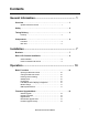
Contents General Information ........................................................ 1 Overview . . . . . . . . . . . . . . . . . . . . . . . . . . . . . . . . . . . . . . . . . . . . . . . . 1 Symbols used in this manual . . . . . . . . . . . . . . . . . . . . . . . . . . . . . . 1 Safety . . . . . . . . . . . . . . . . . . . . . . . . . . . . . . . . . . . . . . . . . . . . . . . . . . . 2 Taking Delivery . . . . . . . . . . . . . . . . . . . . . . . . . . . . . . . . . . . . . . . . . . . 3 Inventory .
Troubleshooting ............................................................ 14 Specifications ................................................................
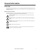
General Information Overview The Rack LCD Console features an 17” or a 19” LCD panel, a full keyboard, and a touch pad in a rackmountable sliding housing. The Rack LCD Console is intended for use with compatible target devices (a KVM switch or server). Symbols used in this manual Note the definitions for the icons here and be observant for them throughout this manual. They are intended to call attention to potential hazards and important information.
Safety Read and adhere to the following important safety considerations when working with the Rack LCD Console. Note: 1. Read all of the instructions. Follow all warnings and instructions. 2. All work must be performed by American Power Conversion (APC®) authorized personnel only. Electrical Hazard: 1. If you are not sure if your power source is compatible with the device requirements, consult your power company. 2.
Taking Delivery Examine the components at the time of delivery to be sure all parts are present and in good working order. Anything missing or damaged must be reported immediately to the shipping firm and to APC. Inventory Description Quantity Easy installation rack mounting installation kit 1 Mounting screws 4 Custom communication cable sets - USB cable, length 6 ft. (1) - PS2 cable, length 6 ft.
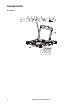
Components Front View EXIT MENU LCD POWER UPGRADE FW UPGRADE NUM LOCK 4 CAPS LOCK SCROLL LOCK RESET Rack LCD Console User Manual aem0351b Stand by
Item Number Component Description EXIT button Left/Down Arrows button Pressing this button moves left or down through the menu and decreases the value when making an adjustment. Right/Up Arrows button Pressing this button moves right or up through the menu and increases the value when making an adjustment. MENU button 1. If the OSD user interface has not been opened, pressing the MENU button initiates it and brings up the Main menu. 2.
Rear View 1 PS/2 - USB CPU aem0351a 0 POWER Item Number Component 6 Description Power Socket Standard 3-prong AC power socket. Power Switch Standard ON/OFF rocker switch Custom Communication Port Port for connecting the Rack LCD Console to the target device (KVM switch or server) using one of the included custom communication cables (PS2 or USB). USB Port USB pass-through from the USB Port on the front of the Rack LCD Console.
Installation Brackets Caution: Use only the hardware provided to install the Rack LCD Console in the rack. 1. Attach the left and right mounting rails to the inside of the rack. The flange that supports the Rack LCD Console station will be to the inside. a. Screw the front flanges to the rack first. na0347a 2. Slide the bars with the rear flanges toward the rack until the flanges make contact with the rack then screw the rear flanges to the rack. 3.
4. Slide the rear attachment sliding brackets along the slide bars until they contact the rear of the Rack LCD Console. Use the supplied M4 x 6 screws to attach the bars to the rear of the Rack LCD Console switch. Fully tighten these screws. 5. Slide the Rack LCD Console open and closed two or three times to be sure it is operating smoothly. aem0348a 6. If the Rack LCD Console is moving properly in the brackets, fully tighten the screws inserted in step 3.
Rack LCD Console Installation Cable installation Connect the target device (KVM switch or server) to the custom communication port on the back of the Rack LCD Console using one of the two custom communication cables (PS2 or USB) that are included. Plug the keyboard, monitor, and mouse connectors to the ports on the target device (KVM switch or server). Note: The maximum distance between the Rack LCD Console and the target device (a KVM switch or server) is 32.8 feet (10m). Power On the Rack LCD Console 1.
Operation Basic Functions Opening the Rack LCD Console To access the console, slide the Rack LCD Console out of the rack and raise the cover. Slide Rail Caution: Do not lean your body weight on the Rack LCD Console. Do not place heavy objects on the Rack LCD Console. Do not use the Rack LCD Console as a shelf. Closing the Rack LCD Console Close the cover and slide the Rack LCD Console into the rack. Powering off and restarting Turn off the power to the Rack LCD using the rear panel power switch.
Monitor settings Setting Explanation Brightness Adjust the brightness level of the screen. Contrast Adjust level of color difference between foreground and background colors. Phase Adjust the phase setting of the screen so that no dark horizontal bands are visible. Clock Adjust the clock setting of the screen so that no dark vertical bands are visible. H-Position Moves the display area left or right. V-Position Moves the display area up or down.
Firmware Upgrade Mode Check www.apc.com regularly to find the latest information and firmware upgrade packages. Note: Do not connect the RJ-11 port marked “Upgrade” to a public telecommunication network. Start the upgrade To download the firmware upgrade package: 1. Turn off the power to the Rack LCD Console. 2. Slide the Firmware switch to RECOVER. 3. Turn on the power to the Rack LCD Console.
Exit firmware upgrade mode 1. Slide the Firmware Upgrade Recovery Switch to the Normal position. 2. Remove the Firmware Upgrade cable from the Firmware Upgrade Port of the Rack LCD Console. 3. Turn the power to the Rack LCD Console OFF and then turn the power ON. Firmware upgrade recovery There are three conditions that call for firmware upgrade recovery: • If the Rack LCD Console’s firmware becomes corrupted and is unable to operate. • When a firmware upgrade is interrupted.
Troubleshooting Symptom Action There are ghost images on the external monitor The distance between the external console and the Rack LCD is too great. The maximum VGA cable distance should not exceed 20m and in some cases may need to be shorter. Replace the VGA cable with one of an appropriately short length. Some characters entered from the keyboard do not display correctly. The keyboard layout setting for the port does not match the keyboard you are using.
Specifications Function Server Connections Connectors Communication ports External mouse Firmware upgrade port Power USB 1.1 hub USB 1.
Radio Frequency Interference Changes or modifications to this unit not expressly approved by the party responsible for compliance could void the user’s authority to operate this equipment. USA—FCC This equipment has been tested and found to comply with the limits for a Class A digital device, pursuant to part 15 of the FCC Rules. These limits are designed to provide reasonable protection against harmful interference when the equipment is operated in a commercial environment.
APC Worldwide Customer Support Customer support for this or any other APC product is available at no charge in any of the following ways: • Visit the APC Web site to access documents in the APC Knowledge Base and to submit customer support requests. – www.apc.com (Corporate Headquarters) Connect to localized APC Web sites for specific countries, each of which provides customer support information. – www.apc.com/support/ Global support searching APC Knowledge Base and using e-support.