
User Manual


8 of 20
5200UZI WHC2_5921 and 5200EZI WHC2_5922 USB ZB Interface and Ethernet ZB Interface User’s Manual
© 2012 Schneider Electric. All Rights Reserved.
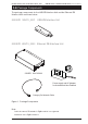
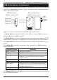
4.0 Switch Buttons and Indicators
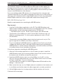
The switch buttons and indicators (LEDs) are used during connection to the network
and also provide status information. Figure 6 shows the location of the buttons and
LEDs on the interface units.
USB ZB Interface
5200UZI WHC2_5921
Ethernet ZB Interface
5200EZI WHC2_5922
Reset button
Setup button
Back side Front side
LEDs
Power LED
ZigBee LED
Power
Ethernet
ZigBee
Reset button
Setup button
Figure 6. Location of switch buttons and LEDs on the interface units.
The Setup Button is used for E-mode actions, such as joining a ZigBee network or
disconnecting from a ZigBee network.
The Reset Button restores the ZigBee settings to the default values. On the EZI ZB
interface unit to reset the IP configuration, you must ‘long-press’ the SETUP button.
The Power LED indicates that the interface unit is connected to a suitable source of
power.
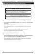
The ZigBee LED shows the current state of the connection to a ZigBee network.
Refer to the table.
The Ethernet LED (Ethernet ZB Interface only) shows the state of the connection to
the local Ethernet network.
Indicator State Meaning
Orange - continuous Not joined to a network.
Orange - flashing slowly Attempting to join a network.
Green - continuous Connected to a network. If no open network is found
within 30 seconds, the LED goes back to the Orange-
continuous mode.
Green - flashing Responding to a ZigBee identity request
Off Connected to an active network.
Red - flashing Failed due to an error (such as multiple networks open).
The LED will flash Red two times slowly and then go back
to Orange-continuous mode.
Orange - flashing rapidly Firmware is being updated--do not unplug