Smart-UPS® RT Uninterruptible Power Supply SURTD 3000/5000 VA 200-240 VAC Tower/Rack-Mount 3U English 2010 APC by Schneider Electric. APC, the APC logo, Smart-UPS and PowerChute are owned by Schneider Electric Industries S.A.S., American Power Conversion Corporation, or affiliated companies. All other trademarks are the property of their respective owners.
Introduction The APC® by Schneider Electric Smart-UPS® RT is a high-performance, uninterruptible power supply (UPS) that provides protection for electronic equipment from utility power blackouts, brownouts, sags and surges. The UPS filters small utility line fluctuations and isolates electronic equipment from large disturbances by internally disconnecting from utility line power.
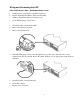
Wiring and Connecting the UPS 5000 VA XLI MODELS ONLY: HARDWIRING INSTRUCTIONS • Wiring must be performed by a qualified electrician. • Install a high magnetic 30/32 A utility circuit breaker. • Adhere to all national and local electrical codes. • Use #10 AWG gauge (5 mm2) wire. 1. 2. 3. Switch the utility circuit breaker OFF. Remove the input access panel. Remove circular knockout. 4.
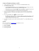
CONNECTING THE BATTERY MODULES AND ATTACHING THE FRONT BEZEL 4
BASIC CONNECTORS The serial connector is to be used for interfacing with APC PowerChute software and terminal emulation software. serial com Use only cables approved by APC. Any other interface cable will be incompatible with the UPS connector. Manual bypass enables the user to manually put connected equipment into bypass mode. normal bypass Emergency Power Off terminal allows the user to connect the UPS to the central EPO system.
CONNECTING EQUIPMENT AND POWER TO THE UPS 1. 2. Connect equipment to the UPS (cables not included for XLJ/XLT/XLTW models). Avoid using extension cords. • 3000 VA XLJ/XLT/XLI/XLTW and 5000 VA XLJ/XLT/XLTW models: Using a power cord, plug the UPS into a two-pole, three-wire, grounded receptacle only. • 3. 4. 5. 5000 VA XLJ models: To draw full 5000 VA from the UPS have a qualified electrician cut off the input plug and hardwire the UPS to the appropriate power panel. Turn on all connected equipment.
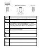
OPERATION SMART-UPS RT FRONT DISPLAY Load Battery Charge Indicator Description Online The Online LED illuminates when the UPS is drawing utility power and performing double conversion to supply power to connected equipment. On Battery The UPS is supplying battery power to the connected equipment. Bypass The Bypass LED illuminates indicating that the UPS is in bypass mode. Utility power is sent directly to connected equipment during bypass mode operation.
Feature Function Cold Start When there is no utility power and the UPS is off, press and hold the power up the UPS and connected equipment. button to The UPS will emit two beeps. During the second beep, release the button. Self-Test Automatic: The UPS performs a self-test automatically when turned on, and every two weeks thereafter (by default). During the self-test, the UPS briefly operates the connected equipment on battery.
USER CONFIGURABLE ITEMS NOTE: SETTINGS ARE MADE THROUGH SUPPLIED POWERCHUTE SOFTWARE, OPTIONAL SMART SLOT ACCESSORY CARDS, OR TERMINAL MODE. FACTORY DEFAULT USER SELECTABLE CHOICES Automatic Self-Test On start-up and every 14 days, thereafter On start-up and every 7 days thereafter On start-up and every 14 days thereafter On start-up only No self-test Set the interval at which the UPS will execute a self-test.
NOTE: SETTINGS ARE MADE THROUGH SUPPLIED POWERCHUTE SOFTWARE, OPTIONAL SMART SLOT ACCESSORY CARDS, OR TERMINAL MODE. FUNCTION FACTORY DEFAULT Low Bypass Point 160 VAC USER SELECTABLE CHOICES DESCRIPTION Output Voltage Setting 200 VAC: 160 - 185 VAC 208 VAC: 160 - 190 VAC 220 VAC: 160 - 195 VAC 230 VAC: 160 - 200 VAC 240 VAC: 160 - 205 VAC Minimum voltage that the UPS will pass to connected equipment during internal bypass operation.
CONNECTING THE EPO (EMERGENCY POWER OFF) OPTION The output power can be disabled in an emergency by closing a switch connected to the EPO. Adhere to National and local electrical codes when wiring the EPO. EPO switch The EPO switch is internally powered by the UPS for use with non-powered switch circuit breakers. The EPO circuit is considered a Class 2 circuit, (UL, CSA standards) and a SELV circuit (IEC standard). Both Class 2 and SELV circuits must be isolated from all primary circuitry.
TERMINAL MODE TO CONFIGURE UPS PARAMETERS 3000 VA models: Terminal Mode is a menu driven interface that enables configuration of the UPS by users not wishing to use PowerChute® software or an optional Network Management Card. Connect the serial cable to the serial com connector on the back of the UPS. If PowerChute software is not installed do not perform steps 1 and 7. 1.
5000 VA models: Terminal Mode is a menu driven interface that enables configuration of the UPS by users not using PowerChute software or the installed Network Management Card interfaces. Connect the serial cable to the serial port on the back of the UPS. If PowerChute software is not installed do not perform steps 1 and 5. For Windows users: STOP the PowerChute® Server using the following steps: • From the Desktop, go to Start => Settings => Control Panel => Administrative Tools => Services.
• Press 2 and ENTER to change the Battery Settings. • 5. Type in the number of external battery packs (four battery modules per pack), and press ENTER. (Number of packs: 1 = 1 SURT192XLBP, 2 = 2 SURT192XLBP etc.) • Press 3 and ENTER to accept the changes. • Press ESC multiple times (5) to return to the main menu. • Press 4 and ENTER to log out.
MAINTENANCE AND TRANSPORT Replacing the Battery Module This UPS has an easy to replace, hot-swappable battery module. Replacement is a safe procedure, isolated from electrical hazards. You may leave the UPS and connected equipment on during the procedure. See your dealer or contact APC at the Web site, www.apc.com for information on replacement battery modules. The battery replacement procedure must include replacing all battery modules in the UPS and connected external battery pack(s).
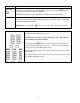
REPLACING BATTERY MODULES X Y Z ] [ ^ \ _ Disconnecting the Battery for Transport Always DISCONNECT THE BATTERY(s) before shipping in compliance with U.S. Department of Transportation (DOT) and IATA regulations. The battery(s) may remain in the UPS. 1. Shut down and disconnect any equipment attached to the UPS. 2. Shut down and disconnect the UPS from the power supply. 3. Unplug the battery connectors. Refer to Replacing Battery modules in this manual.
TROUBLESHOOTING, SERVICE, AND WARRANTY INFORMATION Use the table below to solve minor installation and operation problems. Refer to the APC Web site, www.apc.com for assistance with complex UPS problems. PROBLEM AND POSSIBLE CAUSE SOLUTION UPS WILL NOT TURN ON Battery not connected properly. button not pushed. Check that the battery connectors are fully engaged. Press the button once to power the UPS and the connected equipment. UPS not connected to utility power supply.
PROBLEM AND POSSIBLE CAUSE SOLUTION BYPASS LED ILLUMINATES The bypass switch has been turned on manually or through an accessory. If bypass is the chosen mode of operation, ignore the illuminated LED. If bypass is not the chosen mode of operation move the bypass switch on the back of the UPS, to the normal position. FAULT AND OVERLOAD LEDS ILLUMINATE, UPS EMITS A SUSTAINED ALARM TONE The UPS has ceased sending power to connected equipment.
Service If the UPS requires service do not return it to the dealer. Follow these steps: 1. Review the problems discussed in the Troubleshooting section of this manual to eliminate common problems. 2. If the problem persists, contact APC Customer Support through the APC Web site, www.apc.com. • Note the model number of the UPS, the serial number located on the back of the unit, and the date purchased.
RADIO FREQUENCY WARNINGS This equipment has been tested and found to comply with the limits for a Class A digital device, pursuant to part 15 of the FCC Rules. These limits are designed to provide reasonable protection against harmful interference when the equipment is operated in a commercial environment. This equipment generates, uses, and can radiate radio frequency energy and, if not installed and used in accordance with the instruction manual, may cause harmful interference to radio communications.