
Technical Data Bulletin

19-128
© 2019 Schneider Electric
All Rights Reserved
Pendant Stations Wireless Remote Control System
schneider-electric.us
Refer to Catalog DIA5ED2140103EN
1
3
5
9
9
2
4
6
8
7
10
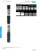
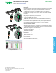
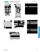
Front view of ZART12D remote
device
15
14
13
12
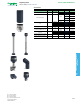
Rear view of remote device
Remote Control Device Description
1–6
Auxiliary buttons (for ZART8D and ZART8L only
buttons 5 and 6 are available)
7
Display (for ZART8L LED display only)
8
E-stop LED
9
OFF/Stop button
10 ON/Start/Horn button
11 Motion buttons
12 Cover
13 RJ45 connector
14 Reset button
15
Trigger button
16
Connector for charging remote device
17 Connector cover
18
E-stop button
16
17
18
Underside view of remote device handle
134 2
Underside view of ZARB●H base station
1356 2
Underside view of ZARB●W base station
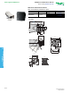
Base Stataion
1
M12 for external antenna[3]
2 Status LEDs
3
M20 for the Safeguarding function input wires[3]
4
62-pin connector[3]
5
M25 for output wires[4]
6
M25 for detected application alarm input wires[3]
7
4 holes for standard mounting on support [3]
7
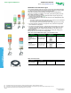
ZARB•W
ZARB•H
7
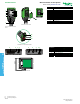
Front view of base station with cover
19
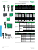
PUSH BUTTONS AND OPERATOR
INTERFACE
[3] Covered by an end cap.
[4] Covered by a cable gland.