Xantrex™ GT250 E 250 kW Grid-Tied Photovoltaic Inverter Planning and Installation Manual www.schneider-electric.
Xantrex GT250 E 250 kW Grid-Tied Photovoltaic Inverter Planning and Installation Manual www.schneider-electric.
Copyright and Contact Trademarks Schneider Electric, the Schneider Electric logo, and Xantrex are trademarks or registered trademarks of the Schneider Electric group of companies. Other trademarks, registered trademarks, and product names are the property of their respective owners and are used herein for identification purposes only. Notice of Copyright Copyright © 2008, 2009, 2010 Xantrex Technology Inc. All rights reserved.
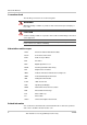
About This Manual Purpose The purpose of this Planning and Installation Manual is to provide explanations and procedures for planning and installing the Schneider Electric Xantrex GT250 E 250 kW Grid-Tied Photovoltaic Inverter. Scope The Manual provides safety guidelines, detailed planning and setup information, and procedures for installing the inverter.
About This Manual Conventions Used The following conventions are used in this guide. WARNING Warnings identify conditions or practices that could result in personal injury or loss of life. CAUTION Cautions identify conditions or practices that could result in damage to the unit or other equipment. Important: These notes describe things which are important for you to know, but not as serious as a caution or warning.
Important Safety Instructions SAVE THESE INSTRUCTIONS - DO NOT DISCARD This manual contains important safety instructions for the Xantrex GT250 E 250 kW Grid-Tied Photovoltaic Inverter (Xantrex GT250 E) that shall be followed during installation and maintenance procedures. WARNING: Shock Hazard Read and keep this Planning and Installation Manual for future reference. Before installing Xantrex GT250 E read all instructions, cautionary markings, and all other appropriate sections of this manual.
Safety Risks WARNING: Shock hazard Parts of the condenser charge will still be energized for a maximum of 20 minutes after being disconnected. Open device cover plates or doors only after the device is disconnected and discharged. Check whether the device is no longer live (DC voltage) including terminals PV+ and PV-. WARNING: Explosion hazard The IGBT module may explode in the event of a major malfunction. Do not operate larger devices while the pivoting part is opened.
Safety General Safety Precautions 1. When installing the Xantrex GT250 E use only components recommended or sold by the manufacturer. Doing otherwise may result in a risk of fire, electric shock, injury to persons, and will void the warranty. 2. Do not attempt to operate the Xantrex GT250 E if it has been dropped, or received more than cosmetic damage during transport or shipping.
Safety Wiring Requirements 1. All wiring methods and materials shall be in accordance with the National Electrical Code ANSI/NFPA 70, European Requirements, as well as all state and local code requirements (for example, DIN / VDE). 2. The Xantrex GT250 E has a three-phase output. 3. The AC power conductor wiring interfacing with the AC terminals in the AC Interface Enclosure (-H0) are located at L1, L2, L3. These terminals requires the use of a crimp-on type ring terminal or compression-type lug.
Safety Operational Safety Procedures Never work alone when servicing this equipment. A team of two is required until the equipment is properly de-energized, locked-out and tagged, and verified deenergized with a meter. Thoroughly inspect the equipment prior to energizing. Verify that no tools or equipment have inadvertently been left behind. Lockout and Tag Safety requirements mandate that this equipment not be serviced while energized.
Safety De-Energize/Isolation Procedure The following procedure should be followed to de-energize the Xantrex GT250 E for maintenance. WARNING The terminals of the DC input may be energized if the PV arrays are energized. In addition, allow 20 minutes for all capacitors within the main Enclosure to discharge after disconnecting the Xantrex GT250 E from AC and DC sources. To isolate the Xantrex GT250 E: 1. Turn the ON/OFF switch to the OFF position. 2. Open the DC interface disconnect switch (-Q11). 3.
Contents Important Safety Instructions - - - - - - - - - - - - - - - - - - - - - - - - - - - - - - - - - - - - - - - - - - - v 1 Introduction Description of the Xantrex GT250 E - - - - - - - - - - - - - - - - - - - - - - - - - - - - - - - - - - - - - - - - - - - - 1–2 Operator Interface Controls - - - - - - - - - - - - - - - - - - - - - - - - - - - - - - - - - - - - - - - - - - - - - - - - - - 1–3 ON/OFF Switch - - - - - - - - - - - - - - - - - - - - - - - - - - - - - - - - - - - - - - - - - - - - - - - -
Contents Remote Communications - - - - - - - - - - - - - - - - - - - - - - - - - - - - - - - - - - - - - - - - - - - - - - - - - Telephone Line Connections - - - - - - - - - - - - - - - - - - - - - - - - - - - - - - - - - - - - - - - - - - - - PC Connection Methods - - - - - - - - - - - - - - - - - - - - - - - - - - - - - - - - - - - - - - - - - - - - - - - Remote Connection (Standard) - - - - - - - - - - - - - - - - - - - - - - - - - - - - - - - - - - - - - - - Direct Connection (Serial) - - - - - - - - -
Figures Figure 1-1 Figure 1-2 Figure 1-3 Figure 1-4 Figure 1-5 Figure 1-6 Figure 1-7 Figure 1-8 Figure 2-1 Figure 2-2 Figure 2-3 Figure 3-1 Figure 3-2 Figure 3-3 Figure 3-4 Figure 3-5 Figure 3-6 Figure 3-7 Figure 3-8 Figure 3-9 Figure 3-10 Figure 3-11 Figure 3-12 Figure 3-13 Figure A-1 Xantrex GT250 E Operator Interface Components- - - - - - - - - - - - - - - - - - - - - - - - - - - 1–3 ON/OFF Switch - - - - - - - - - - - - - - - - - - - - - - - - - - - - - - - - - - - - - - - - - - - - - - - - - - - 1–4 E
xiv
Tables Table A-1 Table A-2 Table A-3 Table A-4 Table A-5 Table A-6 Environmental Specifications- - - - - - - - - - - - - - - - - - - - - - - - - - - - - - - - - - - - - - - - - Electrical Specifications - - - - - - - - - - - - - - - - - - - - - - - - - - - - - - - - - - - - - - - - - - - - Regulatory Specifications - - - - - - - - - - - - - - - - - - - - - - - - - - - - - - - - - - - - - - - - - - - Over/Under Voltage and Over/Under Frequency Ranges - - - - - - - - - - - - - - - - - - - - AC Terminal Bolt
xvi
1 Introduction Chapter 1, “Introduction” provides information about the features and functions of the Xantrex GT250 E 250 kW Grid-Tied Photovoltaic Inverter. This manual is for use by qualified personnel only.
Introduction Description of the Xantrex GT250 E The Xantrex GT250 E 250 kW Grid-Tied Photovoltaic Inverter is a utility interactive, three-phase power conversion system for grid-connected photovoltaic arrays with a power rating of 250 kW. Designed to be easy to install and operate, the Xantrex GT250 E automates start-up, shutdown, and fault detection scenarios.
Operator Interface Controls Operator Interface Controls The Xantrex GT250 E comes in a set of 3 enclosures to house the Electronics described above. The left section is the AC Interface Enclosure (-H0). The center section is the Inverter Enclosure (-H1). The right section is the DC Interface Enclosure (-H2). The 3 enclosures are constructed and delivered as one complete assembly. Operator interface controls are located on the front door of the main inverter Enclosure.
Introduction ON/OFF Switch The Xantrex GT250 E incorporates a maintained position ON/OFF switch located on the right center door, under the main control display. Under normal conditions, the ON/OFF switch is in the ON position. Turning the switch to the OFF position will initiate an immediate controlled shutdown of the Xantrex GT250 E and open both the main AC and DC contactors within the unit. The main AC and DC contactors cannot be closed unless the switch is in the ON position.
Operator Interface Controls Emergency Stop (E-STOP) The Xantrex GT250 E incorporates a maintained position E-STOP pushbutton located on the Inverter Enclosure. Under normal conditions, the E-STOP pushbutton is in the CLOSED (extended) position. Pushing the pushbutton to the OPEN (depressed) position will initiate an immediate controlled shutdown of the Xantrex GT250 E and open both the main AC and DC contactors within the unit.
Introduction AC and DC Disconnect Switches Both AC and DC Interface Enclosure doors are equipped with lockout hasps for personnel safety. The Enclosure doors should not be opened while the Xantrex GT250 E is operating. The switch handles and shafts provide a door interlock for both the AC and DC interface Enclosures. The doors cannot be opened when the switch is in the ON position.
Communication Features and Methods Communication Features and Methods The Xantrex GT250 E provides two types of information to the user: • system status and/or fault information, and • data logging information. System status and fault information can be accessed using the Universal Front Panel Control Unit (UFCU) or a personal computer using the Xantrex Solar Graphic User Interface (GUI) software. Data logging requires the use of a PC using the GUI software.
Introduction LCD Display Universal Front Panel Control Unit (UFCU) Figure 1-5 LCD Display and UFCU Location This information can also be accessed using a personal computer using the GUI software either directly or remotely. Alternatively, the fault reporting can be accomplished using the optional Fax Modem.
Communication Features and Methods Data Logging The inverter stores data values and software metrics for debugging. These values are stored within the CCU2 controller board in non-volatile memory. Data logging requires the use of a PC connection using the Xantrex Solar Graphic User Interface (GUI) software.
Introduction RS232/FO Converter MultiTech® 56K Modem Figure 1-6 MultiTech® 56K Modem and RS232/FO Converter -F36 Surge Arrester Figure 1-7 Surge Arrester Direct Access Connection The Xantrex GT250 E can be directly accessed by a computer. This connection requires using the RS232 Converter kit (Manufacturer p/n: 1-152624-01 KIT, COMM, DIRECT, PC TO CCU). The kit contains an RS232/FO converter configured for PC use with an adapter, a DB9/DB25 serial cable and a fiber optic harness.
Optional Equipment Optional Equipment The following options are available for purchase for use with the Xantrex GT250 E to enhance its communications capability. The additional Xantrex GT250 E options can be field installed. Contact a Schneider Electric distributor for further information on installation options.
1–12
2 Planning Chapter 2, “Planning” provides information to help plan the installation of the Xantrex GT250 E 250 kW Grid-Tied Photovoltaic Inverter. This manual is for use by qualified personnel only.
Planning Overview of Xantrex GT250 E Installation WARNING: Shock Hazard Installations of this equipment should only be performed by qualified technicians. Installers must meet all local and state code requirements for licensing and training for the installation of Electrical Power Systems with AC and DC voltage to 600 volts.
Environmental Requirements Environmental Requirements The following environmental conditions must be established and maintained to ensure the safe and efficient operation and servicing of the Xantrex GT250 E. • Maintain a minimum clearance of 60 cm plus local safety requirements in front of the enclosure for air intake, maintenance and serviceability. • External cabling enters the Xantrex GT250 E from the bottom.
Planning Utility Side Isolation Transformer Requirements The Xantrex GT250 E may be supplied with a custom, high-efficiency, isolation transformer as a separate component. The utility side windings of the isolation transformer are configured Wye and must match the voltage at the utility inter-tie. The Xantrex GT250 E is a balanced, three-phase, current-sourcing inverter and only operates with the presence of a stable utility voltage.
Electrical Diagrams Electrical Diagrams Since installations vary widely, a sample electrical diagram of the Xantrex GT250 E is provided in Figure 2-1. This diagram is to be used for system planning purposes only. For more detailed information, refer to the schematic illustrations inside the door of the enclosure for electrical schematics.
Planning Anchoring the Xantrex GT250 E The Xantrex GT250 E is designed to be installed in an indoor location. It must be placed on and anchored to a level concrete floor or pad. The concrete floor or pad, upon which the Xantrex GT250 E is anchored, must be structurally designed to meet any local, state, or national requirements for weight, seismic, and wind sheer if applicable. Twelve 16 mm holes are provided in the feet of the Enclosure for anchoring to the floor or pad.
3 Installation Chapter 3, “Installation” describes the procedures needed to install the Xantrex GT250 E 250 kW Grid-Tied Photovoltaic Inverter. This section includes unpacking and moving instructions, mounting instructions, and cabling instructions. This manual is for use by qualified personnel only.
Installation Unloading WARNING: Heavy Equipment The Xantrex GT250 E weighs approximately 1160 kg. Attempting to lift the equipment by other than the recommended lifting points may damage the equipment or present a personnel safety hazard and void the warranty. Keep all the doors closed and latched when moving the Enclosures. Leaving the door latches unsecured may result in damage to the unit and void the warranty.
Unloading Removing the Pallet and Moving the Xantrex GT250 E CAUTION: Equipment Damage c To move the Xantrex GT250 E, use a forklift that has a sufficient lift capacity and a 66 cm fork span. Use Figure 3-1 to locate the balance point or center of gravity ( symbol). Center of Gravity Side view Figure 3-1 Center of Gravity Moving with a Forklift To move the Xantrex GT250 E using a forklift: 1. Place the forks of the forklift below the unit at the points specified in Figure 3-2. 2.
Installation Figure 3-2 Forklift Lifting Locations - Underneath Unit Moving with a Crane Ensure you dismantle the top for transport. To move the Xantrex GT250 E with a crane: 1. Attach the crane to the four anchor points on the track. 2. Pay attention to the balance point (center of gravity) sticker. 3. Lift the Enclosure into position. 4. Remove the tracks before operating the Xantrex GT250 E.
Mounting and Anchoring the Units Mounting and Anchoring the Units To mount and anchor the Xantrex GT250 E: 1. Predrill the floor or pad to accept masonry anchors for 12 mm bolts, or ensure it has pre-installed anchoring bolts that will fit the 16 mm mounting holes. See Figure 2-3 on page 2–6. 2. Lift the Xantrex GT250 E from beneath with a forklift or pallet jack as shown in Figure 3-2 on page 3–4, or lift the Xantrex GT250 E from above with a crane as shown in Figure 3-3 on page 3–4.
Installation To Open Access Door: 1. Confirm that the AC Disconnect Switch handle is placed in the OFF (Open) position prior to opening the door. AC Interface 2. Using the key supplied with the unit, turn clockwise to unlock. 3. Pull open from right side. Disconnect Switch To Close Access Door: 1. Confirm that the AC Disconnect Switch handle is placed in the OFF (Open) position prior to closing the door. 2. Close the door. 3. Using the key supplied with the unit, turn counterclockwise to lock.
Wiring - General Wiring - General All wiring methods and materials shall be in accordance with the National Electrical Code ANSI/NFPA 70, European Requirements, as well as all state and local code requirements (for example, DIN / VDE). When sizing conductors and conduits interfacing to the Xantrex GT250 E, both shall be in accordance with the National Electric Code ANSI/NFPA 70, European Requirements, as well as all state and local code requirements (for example DIN / VDE).
Installation Overcurrent Protection Unless provided as part of the Schneider Electric supplied equipment; the AC overcurrent protection for the Utility Interconnect (Grid-tie) must be provided by the installer as part of the Xantrex GT250 E installation.
Wiring - General Grounding System Grounding Install a copper ground rod within 3 ft. (1 m) of the Xantrex GT250 E Enclosures per the National Electric Code ANSI/NFPA 70. The single-point ground for the system is to be made at the ground bar in the AC Interface Enclosure. Ground Bar to be used for the Single Point Ground Figure 3-7 Single-point Ground; Ground Bar Chassis Ground The chassis ground is a copper bus bar in the Main Inverter Enclosure and has a 12 mm bolt for terminating the DC ground.
Installation Wiring - Specific This section provides information for connecting the AC and DC conductors and the ground conductors. Table A-5 and Table A-6 on page A–5 show the specifications of the AC and DC wiring. To connect the transformer to AC Interface Enclosure: 1. Open the door to the AC Interface Enclosure. 2. Route the AC power conductors L1, L2, L3 phase, neutral, and a neutral ground cable through the conduit from the transformer to the AC Interface Enclosure. 3.
Wiring - Specific L1 Phase terminal L3 Phase terminal L2 Phase terminal Figure 3-9 AC Terminal Connections from the Utility AC Control Voltage Terminals (-X2-L1, -X2-L2, X2-PE) Figure 3-10 AC Control Voltage Terminal Connections 152936 3–11 This manual is for use by qualified personnel only.
Installation PV Array Connections To make the connections from the PV Array/combiner to DC Interface Enclosure: 1. Open the door to the DC Interface Enclosure. 2. Route the PV Array cables conductors POSitive (PV+) and NEGative (PV-) through the conduit to the DC Interface Enclosure, entering on the underside. 3. The DC power conductor terminations are made at the PV+, and PVallocations and the ground bar. See Figure 3-11. 4.
Remote Communications Remote Communications The Xantrex GT250 E provides remote communications for system monitoring or data logging through a personal computer using the Xantrex Solar Graphic User Interface (GUI) software. The GUI software provides a windows-based interface program that accesses, monitors, and controls the features and functions of the unit. The GUI also provides additional data logging and tracking features which are not available through the UFCU.
Installation PC Connection Methods The personal computer can be connected the following ways. • direct connection - to serial communication port on the controller board • remote connection - through the modem installed in the Enclosure Remote Connection (Standard) The Xantrex GT250 E comes with a MultiTech™ 56K modem installed.
Remote Communications If connecting the PC directly to the inverter: 1. Procure an RS232/FO Converter kit containing the converter, a DB9/DB25 serial cable and a fiber optic harness. 2. Record the color of the fibers connected to the white(TX) and Grey(RX) connectors of the Factory installed RS232/FO Converter and disconnect them from the Converter. 3. Remove the two covers from the fiber connectors on the new RS232/FO Converter and install them on the Factory installed converter. 4.
3–16
4 Verification Chapter 4, “Verification” provides a checklist to ensure the installation of the Xantrex GT250 E is correct and complete. This manual is for use by qualified personnel only.
Verification Verification Procedure Summary WARNING: Electrocution Hazard This chapter describes specific steps to ensure the installation of the Xantrex GT250 E 250 kW Grid-Tied Photovoltaic Inverter is correct and complete. Failure to adhere to these warnings could result in severe shock or possible death. Exercise extreme caution at all times to prevent accidents. These installation instructions are for use by those familiar and skilled with high voltage procedures.
Visual Inspection of Mechanical Connections Visual Inspection of Mechanical Connections To perform a visual inspection of the Xantrex GT250 E mechanical connections: 1. Ensure that the AC and DC Disconnect Switches, as well as any utility interconnect circuit breakers or main disconnect switches, are opened. ❐ 2. Ensure all anchor bolts and any required seismic bracing is properly tightened and in place. ❐ 3.
4–4
A Specifications Appendix A provides the environmental and electrical specifications for the Xantrex GT250 E 250 kW Grid-Tied Photovoltaic Inverter. This manual is for use by qualified personnel only.
Specifications System Specifications The Xantrex GT250 E has been designed for photovoltaic power systems, which operate within the following specifications. CAUTION: Equipment Damage Operation of the Xantrex GT250 E in a manner other than specified in this manual may cause damage to the Xantrex GT250 E and other system components and will void the terms of the warranty. Environmental Specifications CAUTION The Xantrex GT250 E will be destroyed if stored outside. Only store in dry areas.
System Specifications Electrical Specifications Table A-2 provides the AC and DC specifications for the Xantrex GT250 E. Table A-2 Electrical Specifications Specification Value Suggested Maximum PV Array Power 280 kWp Nominal AC Input Voltage 315 Vac ± 5% Maximum AC Output Current 460 Arms Nominal AC Input Frequency 50 Hz (+0.5 to -0.7 Hz acceptable range) Rated Output Power 250.
Specifications Over Voltage, Under Voltage and Frequency Ranges Table A-4 provides the over voltage, under voltage, over-frequency, and underfrequency detection limits for the Xantrex GT250 E. These detection limits have been factory tested and deemed to be in compliance with requirements for utility interaction. Table A-4 Over/Under Voltage and Over/Under Frequency Ranges Vac Condition (% of Nominal) Voltage Range 50Hza Voltage Range 60Hza Low Range 275 < Vac < 325 275 < Vac < 325 100 ms 283.
System Specifications Bolt Sizing and Torque Requirements Table A-5 provides acceptable bolt sizes, and torque values for AC terminal connections. Table A-5 AC Terminal Bolt Size, and Torque Values Max. # of Conductors per Terminal Bolt (Hardware) Size Torque Requirement s PE (Enclosure Ground) 2 1/M12 75 Nm (55 lb ft) L1, L2, L3 6 3/M12 75 Nm (55 lb ft) -X2-L1, -X2-L2, -X2-PE 1 M3 0.6 – 0.8 Nm (5.
Specifications Dimensions Dimensions in mm 475 675 475 605 2112 2006 Figure A-1 Xantrex GT250 E Dimensions A–6 152936 This manual is for use by qualified personnel only.
Schneider Electric www.schneider-electric.com ☎ North America 1 408 987 6255 ✉ 1 925 245 1022 re.techsupport@schneider-electric.com France 0 825 012 999 fr-re-techsupport@fr.schneider-electric.com Deutschland +49 (0) 180 575 6575 +49 (0) 2102 404 7101 solarservice@de.schneider-electric.com España +34 93 498 7466 +34 93 305 5026 re.techsupport@es.schneider-electric.com L'Italia +39 035 4151111 +39 035415 3200 IT-pronto-contatto@it.schneider-electric.