
Installation manual


Installation
3–14 152936
This manual is for use by qualified personnel only.
PC Connection Methods
The personal computer can be connected the following ways.
• direct connection - to serial communication port on the controller board
• remote connection - through the modem installed in the Enclosure
Remote Connection (Standard)
The Xantrex GT250 E comes with a MultiTech™ 56K modem installed. This allows
monitoring and control of the inverter from a remote office, a home office, motel
room, or any location where a laptop or desktop computer can make a modem
telephone call.
The GUI can dial up the inverter and receive fault report calls from it through a
standard Hayes-compatible, landline modem. When the GUI initiates a call
through the modem at the GUI computer, the inverter’s modem answers the call
and initiates a 9600 baud serial connection, effectively as if the GUI was
connected directly. Or, if the inverter experiences a fault, it will initiate a call to the
GUI and report the fault details.
If connecting to the Inverter remotely using the factory-installed modem:
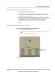
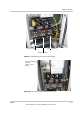
1. Plug the local phone line into the port provided in the Inverter Enclosure
following the instructions on page 3–13.
2. Install the GUI Software. See the Xantrex GT250 E 250 kW Grid-Tied
Photovoltaic Inverter Operation and Maintenance Manual (Part #: 152937) for
installation instructions.
3. Use a Terminal Emulation program on the PC to access the modem.
See the GUI Help Menu "Communication by Modem" for instructions on
setting up the Terminal Emulation program on the computer. See also,
"Connect to Telephone Number" and "Connect to Remote Inverter by Modem"
for additional information.
Direct Connection (Serial)
The direct connection provides the means to use the features of the GUI by
connecting a PC directly to the CCU. This allows field personnel to monitor and
control the inverter from a nearby laptop computer directly connected by a serial
cable. The computer connects to the inverter directly through one of its serial
COM ports running at 9600 baud.
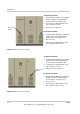
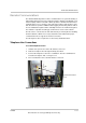
The RS232/FO Converter kit (Manufacturer p/n: 1-152624-01 – KIT, COMM,
DIRECT, PC TO CCU) is required for this connection to change the
communication protocol from ethernet to serial in the Enclosure. The kit contains
an RS232/FO converter configured for PC use with an adapter, a DB9/DB25
serial cable and a fiber optic harness.