
Installation manual
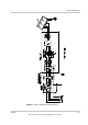

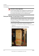
Table Of Contents
- Xantrex™ GT100 E 100 kW Grid-Tied Photovoltaic Inverter
- Xantrex GT100 E 100 kW Grid-Tied Photovoltaic Inverter
- Copyright and Contact
- About This Manual
- Important Safety Instructions
- Contents
- Figures
- Tables
- Introduction
- Planning
- Installation
- Verification and Commissioning
- Specifications
- Commissioning Test Record

Planning
2–4 152364
This manual is for use by qualified personnel only.
Utility Side Isolation Transformer Requirements
The Xantrex GT100 E may be supplied with a custom, high-efficiency, isolation
transformer as a separate component. The utility side winding of the isolation
transformer may be configured Wye or Delta and must match the voltage at the
utility inter-tie. If the utility side winding of the transformer is configured Wye; the
neutral connection of the transformer may be connected to the neutral
connection on the utility interconnect. Connection of this utility-side neutral does
not affect the operation of the inverter. The inverter-side winding of the isolation
transformer may also be configured Wye or Delta. If the inverter-side winding of
the transformer is configured Wye; the neutral connection of the transformer must
be left floating or damage to the inverter will occur. Single-phase, grounded
loads which may be present between the transformer and utility, will maintain
their existing ground reference at the utility distribution transformer.
Electrical Diagrams
Since installations vary widely, a sample electrical diagram of the Xantrex GT100 E
is provided in Figure 2-1. This diagram is to be used for system planning
purposes only.
For more detailed information, refer to the schematic illustrations inside the door
of the enclosure for electrical schematics.
WARNING: Lethal voltage
Grounding the neutral of a Wye-wound transformer may create an “open delta”
condition, depending on the utility configuration. This condition may keep the
Xantrex GT100 E from detecting a loss of phase condition on the utility system,
which may allow potentially lethal voltage to be present on the open-phase
wiring.
CAUTION: Equipment damage
If the isolation transformer neutral terminal is tied to ground, it will cause
irreparable damage to the Xantrex GT100 E. Check local regulations for their
requirements regarding the connection of these neutrals.