
Installation manual


Commissioning Test Record
975-0601-01-01 Revision B C–3
This manual is for use by qualified personnel only.
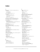
Commissioning Test Record
Step 1. Record and Document Serial Number and Inverter Location
Date and Time of Commissioning:
Transformer Assembly Serial Number:
Xantrex GT500 Serial Number: CCU Board Serial Number:
Installation Name: Technician Name:
Inverter Location (Site ID): Company Name:
Address: Contact Email:
City: State: Zip: Country:
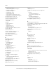
Step 2. Installation and Cable Check
Power Conductors installed correctly: Yes
Terminations are properly torqued: Yes
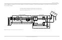
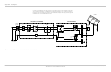
Step 3. Confirm Installation of Throat Kit (Part Number 100-1591-01-01)
Bus bars are installed correctly and
torqued to specification.
Yes Control cables and 120 VAC 8 AWG power
cables are cable-tied and positioned away
from bus bars.
Yes
Control cables P15 and P16 are connected
and latched.
Yes Gasket seals installed on both flange lips
for 360°.
Yes
AC power lines TB13-12 AND TB14-12 are
installed and torqued in TB13 and TB14.
Yes Top/bottom cover centered between inverter
and AC enclosures and covering both seals.
Ground cable connected.
Warning decal positioned to read from front of
system.
Yes
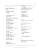
Step 4. Verify AC Utility Voltage at TB1
A-B Measurement: B-C Measurement:
C-A Measurement: Phase Rotation: CW
Step 5. Verify DC PV Voltage at TB3 and TB4
Pos - Neg Measurement: _________VDC. DC Polarity is correct: Yes
TB3-TB5 Ground Measurement: _________VDC.
Step 6. Apply AC Grid Voltage to the Xantrex GT500
Control Power circuits energized: Yes
Notes:
Step 7. Confirm Operation of Keypad and Display
Boots and Displays correctly: Yes PV Disconnect Switch Fault Clears: Yes
Software version (control card SW): Software version (display SW):
Notes:
Step 8. Confirm Write Menu Parameters for AC Limits
Max AC Volts %: Min AC Volts %:
Max AC Frequency: Min AC Frequency:
Max GND Fault:
Notes:
Step 9. Confirm Write Menu Parameters for PV Settings
PV V Start: PV T Start:
PV P Stop: PV T Stop:
Notes: