
Installation manual

General Wiring Requirements
975-0601-01-01 Revision B 3–21
This manual is for use by qualified personnel only.
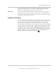
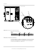
The auxiliary power interface terminals (TB6-1 and TB6-3) are NEMA type box-
lug terminals that require the use of solid or stranded copper wire only. See
Figure 3-18 on page 3–24 for the location of these terminals.
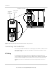
DC Interface The DC terminals (TB3, TB4, and TB5 [PV GND]) in the inverter assembly are
provided with sixteen holes for bolts for securing conductors terminated with
crimp-on type ring-terminals or compression-type lugs. See Figure 3-20 on page
3–26 for the location of these terminals.
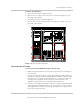
Equipment Grounding
The chassis ground terminal (TB2) is a copper bus bar in the AC interface and
has four holes for bolts for terminating the equipment grounding conductors. The
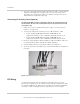
ground conductor size depends on the rating or setting of the overcurrent
protective device provided in the installation for protection of the AC output
circuit and whether the conductor serves as a ground electrode conductor (GEC)
for either the AC or DC systems. If the conductor is also serving as the DC GEC,
the array short circuit current must be considered in sizing the GEC. Consult
applicable installation codes. The Xantrex GT500’s internal circuit breaker has its
long delay trip set to either 750 Arms (Xantrex GT500 480 and Xantrex GT500
480 PG) or 600 Arms (Xantrex GT500 600 and Xantrex GT500 600 PG). The
equipment ground terminal (TB2) is marked with .