
Installation manual

Installation
3–22 975-0601-01-01 Revision B
This manual is for use by qualified personnel only.
Connecting the Conductors
This section provides information for connecting the AC and DC conductors and
the ground conductors. Table A-6 and Table A-5 show the specifications of the
AC and DC wiring.
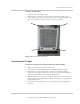
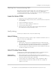
AC Wiring
To help protect service personnel from accidentally touching live electrical
circuits, barriers are installed over the AC and DC electrical wiring compartments
inside the Xantrex GT500. If the AC barrier from the left side of the transformer
assembly has been re-installed, follow the first two steps below to remove it
again.
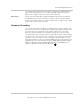
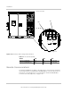
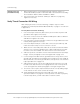
Figure 3-16 Single-point ground; ground bar and AC utility terminals
GND BUS TB2
CB4 (AUX
control
power CB)
CB3 (control
power CB)
CB1
TB1-C
TB1-B
TB1-A
Transformer assembly