
Installation manual

Connecting the Conductors
975-0601-01-01 Revision B 3–23
This manual is for use by qualified personnel only.
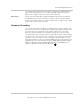
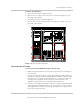
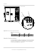
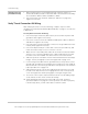
To remove the AC barriers:
1. Open the transformer assembly’s left door.
2. Remove all four screws shown circled on the left side of Figure 3-17, and
then slide out the barrier.
3. Open the transformer assembly’s right door.
4. Remove all six screws shown circled on the right side of Figure 3-17, and
then slide out the barrier.
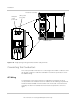
Connecting the AC Output
To connect the Xantrex GT500 AC output to the AC utility:
1. Make sure the AC barrier from the left side of the transformer assembly has
been removed.
2. Connect the AC power conductors at the TB1-A (A phase), TB1-B (B phase),
and TB1-C (C phase) terminals using appropriate hardware. Cables to these
terminals must use a crimp-on type ring terminal or compression-type lug.
See Figure 3-16 on page 3–22 for the location of these terminals. See
Table A-6 on page A–6 for bolt sizing and torque requirements.
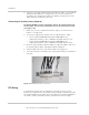
3. Connect the AC equipment ground conductors at the ground terminal (TB2)
using appropriate hardware. Cables to these terminals must use a crimp-on
type ring terminal or compression-type lug. See Figure 3-16 on page 3–22 for
the location of these terminals.
Figure 3-17 Removing the AC barriers