
Installation manual

Installation
3–24 975-0601-01-01 Revision B
This manual is for use by qualified personnel only.
4. If you are sourcing AC auxiliary power externally, proceed to “Connecting AC
Auxiliary Power (Optional)” on page 3–24. If not, close the transformer
assembly’s door, and then proceed to “DC Wiring” on page 3–24. The AC
barrier will be re-installed in a later step.
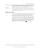
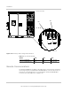
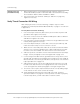
Connecting AC Auxiliary Power (Optional)
The Xantrex GT500 is factory-configured to take its AC auxiliary power from
the AC output. To source the control power from an external source instead
(see Figure 3-18):
1. Make sure you have completed the first two steps in “To remove the AC
barriers:” on page 3–23.
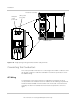
2. Connect the single-phase auxiliary source to TB6 terminals 1 and 3:
• For the Xantrex GT500 480 and Xantrex GT500 480 PG, the
single-phase auxiliary source is 480 VAC and rated minimum 11 A.
• For the Xantrex GT500 600 and Xantrex GT500 600 PG, the
single-phase auxiliary source is 600 VAC and rated minimum 8.5 A.
3. Move the jumper between TB6-4 and TB6-5 to TB6-5 and TB6-6, and move
the jumper between TB6-7 and TB6-8 to TB6-8 and TB6-9.
4. Torque all TB6 terminals as specified in Table A-9 on page A–6.
5. Close the transformer assembly’s door. The AC barrier will be re-installed in a
later step.
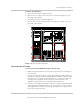
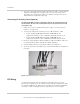
DC Wiring
To help protect installers from accidentally touching live electrical circuits,
barriers are installed over the AC and DC electrical wiring compartments inside
the Xantrex GT500. The DC barrier was removed when the Xantrex GT500 was
anchored. If it was re-installed, follow the steps below to remove it again.
Figure 3-18 Auxiliary power connections