
Installation manual

Connecting the Conductors
975-0601-01-01 Revision B 3–25
This manual is for use by qualified personnel only.
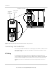
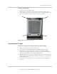
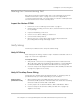
To remove the DC barrier:
1. Open the inverter assembly’s door.
2. Remove all four screws as shown in Figure 3-19, and then slide out the
barrier. Note that the two top screws are not visible in the photograph. They
are on top of the barrier, in line with the screws on the bottom.
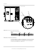
Connecting the PV Input
To make the connections from the PV array to the Xantrex GT500:
1. Make sure the DC barrier has been removed.
2. Re-install the cable gland plates with the original hardware provided.
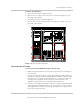
3. Make terminations for the DC power conductor at TB3, TB4, and TB5
(PV ground). See Figure 3-20 for the location of the terminals and Table 3-1
for DC terminal polarity for each Xantrex GT500 model.
4. Make terminations for the positive, negative, and ground conductors within
the DC interface using appropriate hardware. See Table A-5 on page A–5 for
torque requirements.
5. Close the inverter assembly’s door. The DC barrier will be re-installed in a
later step.
Figure 3-19 Removing the DC barrier