
Installation manual

Starting the Commissioning Test
975-0601-01-01 Revision B 4–3
This chapter is for use by qualified personnel and authorized service personnel only.
Starting the Commissioning Test
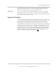
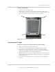
Enter all the information required under “Step 1. Record and Document Serial
Number and Inverter Location” on page C–3 on the form in Appendix C,
“Commissioning Test Record”. The serial number is located on a label placed on
the lower-left front of the inverter assembly’s door.
Inspect the Xantrex GT500
1. Perform the “Lock-out and Tag-out Procedure” on page xi.
2. Visually inspect mounting, enclosures, doors, and other external components
for any damage.
3. Inspect all field wiring connections.
4. Check for loose cables, rubbing, or interference.
5. Correct and record any defects.
6. Remove any tools or other objects that should not be present before
proceeding with the wiring and voltage checks.
Verify Wiring
Follow the procedures below to verify AC and DC wiring.
Verify AC Wiring
After verifying the AC wiring, complete “Step 2. Installation and Cable Check” on
page C–3 on the form in Appendix C.
To verify AC wiring:
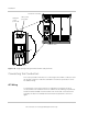
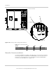
1. Verify that AC connections to the utility grid have been made at terminals
TB1-A, B, and C. Verify that an equipment ground wire is connected between
the Xantrex GT500’s AC ground bus bar TB2 and the site earth ground.
2. Check the torque of AC and ground terminals at TB1 and TB2 (see Table A-6
on page A–6). Tighten as necessary.
Verify AC Auxiliary Power Wiring
Follow either the “Auxiliary power provided externally” or “Auxiliary power not
provided externally” procedure, depending on your installation.
Auxiliary power
provided externally
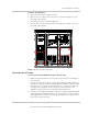
1. When auxiliary power is provided externally, verify the connections to
terminal block TB6 (located on internal left wall of the transformer assembly)
have been made at terminals TB6-1 and TB6-3.
2. Confirm jumpers are located from TB6-5 to TB6-6 and TB6-8 to TB6-9.
3. Check the torque of the terminals at TB6 (see Table A-7 on page A–6).
Tighten as necessary.