
Installation manual

Commissioning
4–4 975-0601-01-01 Revision B
This chapter is for use by qualified personnel and authorized service personnel only.
Auxiliary power not
provided externally
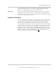
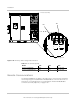
1. When auxiliary power is not provided externally, verify the jumpers on
terminal block TB6 (located on internal left wall of the transformer assembly)
are located from TB6-4 to TB6-5 and TB6-7 to TB6-8.
2. Check the torque of the terminals at TB6 (see Table A-7 on page A–6).
Tighten as necessary.
Verify Throat Connection Kit Wiring
After verifying the throat connection kit wiring, complete “Step 3. Confirm
Installation of Throat Kit (Part Number 100-1591-01-01)” on page C–3 on the form
in Appendix C.
To verify throat connection kit wiring:
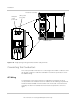
1. Check the torque of fasteners (30 locations) at each end of the phase and
ground bus bars. Tighten if necessary.
2. Check the connection of the two 120 VAC 8 AWG power cables at TB13-12
and TB14-12. Tighten if necessary.
3. Check the throat cover ground cable connection to the ground bus bar in the
inverter (TB7). Tighten if necessary.
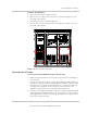
4. Check the 10-pin and 16-pin control cable connectors (P15 and P16), and
make sure that the clamp on each connector is secure.
5. Make sure the control and power cables are secured such that there will be
at least 1 inch of clearance between these cables and bus bars even after
the throat covers are installed. The cables must not touch the bus bars.
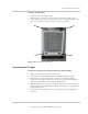
6. Slide the top throat cover down over the inverter and transformer assembly’s
flanges. See the photograph on the left of Figure 3-10 on page 3–14.
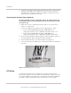
7. Connect the ground cable from the ground bus bar to the top throat cover’s
ground stud. See Figure 3-13 and Figure 3-14 on page 3–16. Use an M8 nut
with star washer to secure the ground cable to the top throat cover, and then
torque per Table A-7 on page A–6.
8. Slide the bottom throat cover up from underneath the top throat cover until
the tabs on the bottom throat cover engage with the slots on the top throat
cover. See Figure 3-13 and the photograph on the right of Figure 3-10.
9. To lock the covers in place, adjust the bottom throat cover by sliding it right
or left until the six holes for the screws are lined up.
10. Install six Belleville washers and socket head cap screws. Torque as
specified in Table A-7 on page A–6. If the top throat cover was not properly
locked in step above, you will not be able to install the screws.