
Installation guide

Installation
2–6 975-0540-01-01 Revision B
This guide is for use by qualified personnel only.
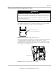
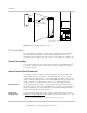
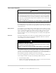
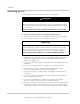
Removing Knockouts
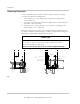
Fourteen knockouts are provided for conduit or cable entry into the charge
controller (see Figure 2-4 and Figure 2-5):
• Three single (one on each side and one on the back) for battery wires:
1.73 in. (44.0 mm).
• Two single on the back and six dual on the sides (three on each side) for PV
array wires: 1.38 in. (35.0 mm).
• Three dual (one on each side and one on the back) for routing BTS and
network cables: 1.11 in. (28.2 mm).
When removing knockouts, make sure no metal shavings or fragments fall into
the wiring compartment. Use bushings or conduits to help protect the wiring from
damage from rough edges around the knockout holes.
CAUTION
CHARGE CONTROLLER DAMAGE
Do not drill, cut, or punch holes in the charge controller. Use only the
knockouts provided for conduit entry.
Failure to follow these instructions can result in equipment damage.
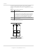
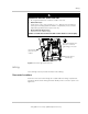
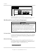
Figure 2-4 Knockout dimensions
26.4
(1.03)
29.0 (1.14)
45.4 (1.78)
55.2 (2.17)
85.5 (3.37)
22.8
(0.90)
62.3 (2.45)
82.8
3.26)
102.5 (4.03)
35.0 (1.38)
85.0 (3.35)
110.0 (4.33)
169.0 (6.65)
22.8 (0.90)
146.5 (5.18)
28.2
(1.11)/
22.2(0.87)
DUAL KNOCKOUT
35.0
(1.38) KNOCKOUT 2PL
44.0
(1.73) KNOCKOU
T
150.0 (5.90)
6.5 (0.25)