
Datasheet

14
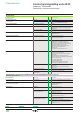
Characteristics
Environment
Protective treatment
standard version
“TH” treatment
Ambient air temperature
around the device
Storage °C - 40…+ 70
Operation °C - 25…+ 70: LED and neon bulb versions
- 25…+ 55: incandescent bulb version
Electric shock protection Conforming to IEC 61140 Class I
Degree of protection Conforming to IEC 60529 IP 66
IP 69 K (Selector switches and multiple-headed
pushbuttons)
Conforming to NEMA NEMA type 4X and 13, unless otherwise stated
Resistance to high pressure washer Pa 70 x 10
5
(70 bar); distance: 0.1 m
Temperature: 55°C
Mechanical shock protection Conforming to IEC 50102 Non illuminated heads: IK 03
Illuminated heads: IK 05
Selector switch heads: IK 06
Conforming to standards EN/IEC 60947-1, EN/IEC 60947-5-1,
EN/IEC 60947-5-4, EN/IEC 60947-5-5,
EN/IEC 60204-1 and EN/ISO 13850:2006
(Emergency stop trigger action and mechanical
latching pushbuttons, see page 30),
IEC 60364-5-53 (Emergency switching off
mechanical latching pushbuttons,
see page 31)
JIS C 4520, UL 508, CSA C22-2 n° 14
Product certications UL Listed, CSA Standard single contacts with screw clamp and
spring terminals: A600; Q600
Double contacts with screw clamp terminals:
A600; Q600
Light blocks with screw clamp terminals
Joystick controllers XD4 PA/ZD4 PA: A600; R300
Special contact blocks:
ZBE 201: A300; Q300
ZBE 202: A600; Q600
Single contacts for high power switching:
ZBE 501 and ZBE 502: A300; P300
v
v
v
UL Recognized, CSA Standard single contacts for plug-in connector:
A300; R300
Standard contacts for printed circuit board:
B300; R300
BV, RINA, LROS, DNV, GL
Standard single contacts and double contacts with
screw clamp or spring terminals:
Terminal referencing Conforming to EN 50005
and EN 50013
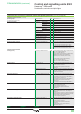
Characteristics of contact or combined contact and signalling functions (see page 18)
Mechanical characteristics
Contact operation N/C or N/O Slow break
Positive operation Conforming to
EN/IEC 60947-5-1 appendix K
All functions incorporating a N/C contact have
positive opening operation
Operating travel
(to change the electrical state)
Pushbutton mm Changing N/C state: 1.5
Changing N/O state: 2.6
Total travel: 4.3
Operating force Pushbutton N Changing N/C state: 3.5
Changing N/O state: 3.8
Additional contact only
(extra to change state)
N Single N/C contact: 2
Single N/O contact: 2.3
N Double N/C contact: 3.4
Double N/O contact: 5
Double contact N/C + N/O: 4.6
Emergency stop or Emergency
switching off with N/C + N/O
N Standard push-pull: 45
Trigger action push-pull: 50
N Standard turn to release and key release: 40
Trigger action turn to release and key release,
“trigger action”: 44
General:
page 6
References:
page 20
Dimensions:
page 68
General:
page 6
References:
page 20
Dimensions:
page 68
General:
page 6
References:
page 20
Dimensions:
page 68
General:
page 6
References:
page 20
Dimensions:
page 68
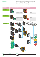
Control and signalling units Ø 22
Harmony
®
XB4 metal
Pushbuttons, switches and pilot lights
1
2
3
4
5
6
7
8
9
10