975-0400-01-01_Rev-H(XW-MPPT60-150).book Page i Thursday, November 23, 2017 11:48 AM Conext™ MPPT 60 150 Solar Charge Controller (865-1030-1) Installation and Owner’s Guide 975-0400-01-01 Revision H November 2017 Owner’s Manual http://solar.schneider-electric.
975-0400-01-01_Rev-H(XW-MPPT60-150).
975-0400-01-01_Rev-H(XW-MPPT60-150).book Page i Thursday, November 23, 2017 11:48 AM Conext™ MPPT 60 150 Solar Charge Controller Installation and Owner’s Guide http://solar.schneider-electric.
975-0400-01-01_Rev-H(XW-MPPT60-150).book Page ii Thursday, November 23, 2017 11:48 AM Copyright and Contact Copyright © 2013-2017 Schneider Electric. All Rights Reserved. All trademarks are owned by Schneider Electric Industries SAS or its affiliated companies.
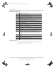
975-0400-01-01_Rev-H(XW-MPPT60-150).book Page iii Thursday, November 23, 2017 11:48 AM About This Guide Purpose The purpose of this Guide is to provide explanations and procedures for installing, configuring, operating, and troubleshooting the Conext MPPT Solar Charge Controller (solar charge controller). Scope This Guide provides safety guidelines, detailed planning and setup information, procedures for installing the unit, as well as information about operating and troubleshooting the unit.
975-0400-01-01_Rev-H(XW-MPPT60-150).
975-0400-01-01_Rev-H(XW-MPPT60-150).book Page v Thursday, November 23, 2017 11:48 AM Important Safety Instructions READ AND SAVE THESE INSTRUCTIONS - DO NOT DISCARD This guide contains important safety instructions for the Conext MPPT Solar Charge Controller that must be followed during installation procedures. Read and keep this Installation and Owner’s Guide for future reference.
975-0400-01-01_Rev-H(XW-MPPT60-150).book Page vi Thursday, November 23, 2017 11:48 AM Safety Safety Information 1. Before installing or using this device, read all instructions and cautionary markings located in (or on) this guide, the unit, the batteries, PV array, and any other equipment used. 2. All electrical work must be done in accordance with local, national, and/or international electrical codes. 3. This product is designed for indoor mounting only.
75-0400-01-01_Rev-H(XW-MPPT60-150).book Page vii Thursday, November 23, 2017 11:48 AM Safety WARNING LIMITATION ON USE The Conext MPPT Solar Charge Controller is not intended for use in connection with life support systems or other medical equipment or devices. Failure to follow these instructions can result in death or serious injury. CAUTION BURN HAZARD Do not touch the solar charge controller’s heatsink during operation or before servicing immediately after ceasing operation.
975-0400-01-01_Rev-H(XW-MPPT60-150).book Page viii Thursday, November 23, 2017 11:48 AM Safety viii • Remove all jewelry before working with batteries. • Wear rubber gloves and boots when handling batteries. • Never work alone. Have someone assist you with the installation or be close enough to come to your aid when working with batteries. • Always use proper lifting techniques when handling batteries. • Always use identical types of batteries. • Never install old or untested batteries.
975-0400-01-01_Rev-H(XW-MPPT60-150).book Page ix Thursday, November 23, 2017 11:48 AM Safety FCC Information to the User This equipment has been tested and found to comply with the limits for a Class B digital device, pursuant to part 15 of the FCC Rules. These limits are designed to provide reasonable protection against harmful interference when the equipment is operated in a residential environment.
975-0400-01-01_Rev-H(XW-MPPT60-150).
975-0400-01-01_Rev-H(XW-MPPT60-150).
975-0400-01-01_Rev-H(XW-MPPT60-150).
975-0400-01-01_Rev-H(XW-MPPT60-150).
975-0400-01-01_Rev-H(XW-MPPT60-150).
975-0400-01-01_Rev-H(XW-MPPT60-150).book Page 1 Thursday, November 23, 2017 11:48 AM 1 Introduction Chapter 1 describes features and functions of the Conext MPPT Solar Charge Controller. It includes: • Features • Maximum Power Point Tracking • Charge Controlling • Auxiliary Output Functions • Automatic PV Array Night Disconnect 975-0400-01-01 Revision H This manual is for use by qualified personnel only.
975-0400-01-01_Rev-H(XW-MPPT60-150).book Page 2 Thursday, November 23, 2017 11:48 AM Introduction Features The Conext MPPT Solar Charge Controller (solar charge controller) is a photovoltaic (PV) charge controller that tracks the maximum power point of a PV array to deliver the maximum available current for charging batteries. The solar charge controller can be used with 12-, 24-, 36-, 48-, and 60-volt DC battery systems.
975-0400-01-01_Rev-H(XW-MPPT60-150).book Page 3 Thursday, November 23, 2017 11:48 AM Maximum Power Point Tracking • Over-temperature protection and power derating when output power and ambient temperature are high. • Battery Temperature Sensor (BTS) to provide automatically temperaturecompensated battery charging. If the BTS is lost or damaged, a replacement can be ordered from Schneider (part number 808-0232-02). • Xanbus communications network.
975-0400-01-01_Rev-H(XW-MPPT60-150).book Page 4 Thursday, November 23, 2017 11:48 AM Introduction Charge Controlling The solar charge controller can regulate PV array current for charging batteries at 12, 24, 36, 48, and 60 volts. It produces 60 amps of charging current and up to 3500 W (on 60-volt batteries) of charging power. + + – + – + – – Figure 1-3 PV Charge Controller The solar charge controller controls how the batteries are charged by the DC source (the PV array).
975-0400-01-01_Rev-H(XW-MPPT60-150).book Page 5 Thursday, November 23, 2017 11:48 AM Charge Controlling Three-Stage Battery Charging The three-stage charging process results in more efficient charging compared to on-off relay type or constant voltage solid-state regulators. The final float stage reduces battery gassing, minimizes electrolyte loss, and ensures complete battery recharging. Battery voltage and current vary during the three-stage charging process as shown in Figure 1-4.
975-0400-01-01_Rev-H(XW-MPPT60-150).book Page 6 Thursday, November 23, 2017 11:48 AM Introduction Bulk State Bulk/Boost Voltage Voltage Absorption State Float State Absorption Voltage Float Voltage Recharge Voltage Boost Timer 1hr fixed Time Max Absorb Time - dflt 3 hrs (adjustable 1 min - 8 hrs ) Current Max Current Limit Absorption Exit Current Threshold = 2% of programmed AH capacity Time Figure 1-4 Three-stage Battery Charging Cyclea a.
975-0400-01-01_Rev-H(XW-MPPT60-150).book Page 7 Thursday, November 23, 2017 11:48 AM Charge Controlling Note: This note is applicable to Figure 1-4 and Figure 1-5. 1. When the charge cycle is interrupted, the charger will restart charging at the beginning of the multi-stage algorithm. 2. Exit Current Threshold can be effectively disabled by programming the amp hour capacity to zero. In this case, Absorption will only exit once the Max Absorption timer expires. 3.
975-0400-01-01_Rev-H(XW-MPPT60-150).
975-0400-01-01_Rev-H(XW-MPPT60-150).book Page 9 Thursday, November 23, 2017 11:48 AM Charge Controlling Battery Temperature Compensation The Battery Temperature Sensor (BTS) automatically adjusts the charging process of the solar charge controller. With the BTS installed, the solar charge controller increases or decreases the battery charging voltage depending on the temperature of the battery to optimize the charge to the battery and to protect it from over-charge or damage.
975-0400-01-01_Rev-H(XW-MPPT60-150).book Page 10 Thursday, November 23, 2017 11:48 AM Introduction Auxiliary Output Functions The solar charge controller has a configurable auxiliary output (producing 5 to 13 volts at up to 200 milliamps) to drive a relay for load control or to turn on devices such as vent fans or indicator alarms. The auxiliary output can be configured to perform only one function at a time.
975-0400-01-01_Rev-H(XW-MPPT60-150).book Page 11 Thursday, November 23, 2017 11:48 AM Automatic PV Array Night Disconnect Automatic PV Array Night Disconnect At night, or when the PV array voltage is less than the battery voltage, the solar charge controller opens an internal relay to prevent battery current from flowing back to the PV array. In this mode of operation the solar charge controller draws minimal power from the battery.
975-0400-01-01_Rev-H(XW-MPPT60-150).
975-0400-01-01_Rev-H(XW-MPPT60-150).book Page 1 Thursday, November 23, 2017 11:48 AM 2 Installation Chapter 2 contains information and procedures to install the Conext MPPT Solar Charge Controller. It includes: • Materials List and Tool Requirements • PV Array Requirements • Mounting • Grounding • Wiring • Installing the Battery Temperature Sensor • Commissioning Before installing the solar charge controller, read this entire chapter.
975-0400-01-01_Rev-H(XW-MPPT60-150).
975-0400-01-01_Rev-H(XW-MPPT60-150).book Page 3 Thursday, November 23, 2017 11:48 AM Mounting Effects of array voltages outside of the MPPT operational window are shown in Table 2-1. Table 2-1 MPPT Operational Window Charge Controller Mode Voltage Effect of Array Voltage Voc < Vbatt (system battery voltage) Charge controller does operate. Low Light VMPP < Vbatt Harvest of solar energy less than optimal. Charging VMPP = Vbatt to 120 VDC Maximum harvest of solar energy.
975-0400-01-01_Rev-H(XW-MPPT60-150).book Page 4 Thursday, November 23, 2017 11:48 AM Installation Flammable or combustible materials are defined as “any material containing wood, compressed paper, cellulose, plant fibers, plastics, liquids, or other material that will ignite and burn, whether flame-proofed or not” according to the NFPA. Flammable liquids are defined as “any liquid whose flash point does not exceed 100 °F (38 °C).” Examples of flammable liquids are gasoline, methanol, and ether.
975-0400-01-01_Rev-H(XW-MPPT60-150).book Page 5 Thursday, November 23, 2017 11:48 AM Mounting Table 2-2 Minimum Clearance Requirements Location Minimum Clearance Above 6 inches (150 mm). When units are mounted in a vertical stack, the topmost unit must maintain the minimum clearance to the nearest surface. Note: Minimum clearances can be ignored when mounting two units on the side of the Conext Power Distribution Panel (PDP). For more information, see the Conext XW+ Inverter/Charger Installation Guide.
975-0400-01-01_Rev-H(XW-MPPT60-150).book Page 6 Thursday, November 23, 2017 11:48 AM Installation Remove screws to access the wiring terminals. Figure 2-2 Removing the Wiring Compartment Cover Removing Knockouts Six dual and two single knockouts are provided for routing battery, PV array, BTS, and network cables into the solar charge controller. Use bushings or conduits to protect the wiring from damage from rough edges around the knockout holes.
975-0400-01-01_Rev-H(XW-MPPT60-150).book Page 7 Thursday, November 23, 2017 11:48 AM Mounting Keyhole slot for wall mounting 73 (2 7/8) 323 (12 3/4) 280 (11) Additional mounting holes 368 (14 1/2) Ø 6.35 (1/4) 60 (2 3/8) 53 (2 1/16) 118 (4 5/8) 14 (9/16) 26.5 (1) 146 (5 3/4) 138 (5 7/16) All measurements in mm (in.) Figure 2-3 Dimensions and Knockout Locations Single knockouts are intended for BTS and network cables DUAL KNOCKOUT 34.52 (1 3/16) & 27.78 (1 1/16) 2 PL DUAL KNOCKOUT 34.
975-0400-01-01_Rev-H(XW-MPPT60-150).book Page 8 Thursday, November 23, 2017 11:48 AM Installation Mounting the Charge Controller The solar charge controller is vertically mounted using three #10 × ½-inch or #12 × ½-inch (12.5 mm) pan-head screws. To mount the solar charge controller: 1. Remove the wiring compartment cover. 2. Mark the location of the keyhole slot on the wall. 3. Secure the top mounting screw in the location marked. Leave the screw head backed out approximately ¼ inch (6 mm). 4.
975-0400-01-01_Rev-H(XW-MPPT60-150).book Page 9 Thursday, November 23, 2017 11:48 AM Grounding Grounding The charge controller can be configured to be compatible with negativegrounded and ungrounded PV systems. For information about routing the ground connection, see Figure 2-10. The maximum size of the ground conductor is #6 AWG (16 mm2).
975-0400-01-01_Rev-H(XW-MPPT60-150).book Page 10 Thursday, November 23, 2017 11:48 AM Installation NOTICE EQUIPMENT DAMAGE The factory default configuration of the solar charge controller will ground the PV array negative to the chassis ground through the internal PV-GFP fuse. Disable the PV-GFP circuit for ungrounded PV arrays. Failure to follow these instructions can damage the equipment. This symbol identifies the protective conductor (grounding) connection.
975-0400-01-01_Rev-H(XW-MPPT60-150).book Page 11 Thursday, November 23, 2017 11:48 AM Grounding Enabled Disabled Figure 2-7 PV Negative Ground Jumper Location Installing a Positive-Grounded Battery System The solar charge controller’s internal design has a built-in fuse—rated at 1 A, 600 V—which grounds both the PV negative and battery negative conductors and provides PV ground-fault protection (PVGFP) to the system.
975-0400-01-01_Rev-H(XW-MPPT60-150).book Page 12 Thursday, November 23, 2017 11:48 AM Installation These voltage levels on both battery and auxiliary outputs are considered safe, extra-low voltages and do not present a hazard as long as the PV terminals are kept floated or ungrounded. Follow the instructions in Chapter 2, “Installation” for connecting the PV array and battery to the unit. Next, follow these steps for a safe, negative voltage reference connection: 1.
975-0400-01-01_Rev-H(XW-MPPT60-150).book Page 13 Thursday, November 23, 2017 11:48 AM Grounding Enabled Disabled Figure 2-8 Jumper Location PV Connection and Auxiliary Lines WARNING haz FIRE HAZARD Do not ground the negative conductor of the auxiliary circuit. Failure to follow these instructions could result in death or serious injury. The PV array must not be grounded in either its positive or negative terminal. Do not attempt to ground the PV+ terminal to have a common ground with the battery.
975-0400-01-01_Rev-H(XW-MPPT60-150).book Page 14 Thursday, November 23, 2017 11:48 AM Installation Wiring Important: Installations must meet all local electrical codes.This equipment should only be installed by a qualified electrician or a Certified Renewable Energy System Installer. WARNING ELECTRICAL SHOCK HAZARD Isolate positive and negative PV and battery circuits before wiring. Failure to follow these instructions can result in death or serious injury.
975-0400-01-01_Rev-H(XW-MPPT60-150).book Page 15 Thursday, November 23, 2017 11:48 AM Wiring Current Rating The solar charge controller PV input is rated for 60 A maximum Isc. Since PV outputs can vary due to the array size or sunlight angle, the safe minimum wire size must be chosen for maximum array short-circuit current. Consult PV array manufacturer specifications.
975-0400-01-01_Rev-H(XW-MPPT60-150).book Page 16 Thursday, November 23, 2017 11:48 AM Installation WARNING EQUIPMENT DAMAGE Do not connect an array capable of delivering over 60 A Isc to the solar charge controller. Wire sizes larger than #6 AWG (16 mm2) may be used to reduce resistive losses but should not be installed directly into the solar charge controller. Use a splicer block or similar to connect wires of different gauges together. Follow manufacturer’s recommendations for torque and mounting.
975-0400-01-01_Rev-H(XW-MPPT60-150).
975-0400-01-01_Rev-H(XW-MPPT60-150).book Page 18 Thursday, November 23, 2017 11:48 AM Installation Connecting the Charge Controller The following procedure is illustrated in Figure 2-10. WARNING ELECTRIC SHOCK HAZARD The PV array will produce a hazardous voltage with even a small amount of light. Appropriate measures must be taken to prevent electric shock. If the PV-GFP is enabled, do not connect the battery negative to ground.
975-0400-01-01_Rev-H(XW-MPPT60-150).book Page 19 Thursday, November 23, 2017 11:48 AM Wiring NOTICE REVERSE POLARITY DAMAGE Before making the final DC connection or closing the DC breaker or disconnect, check cable polarity at both the battery and the solar charge controller. Positive (+) must be connected to positive (+). Negative (–) must be connected to negative (–). Failure to follow these instructions can damage the equipment. 8.
975-0400-01-01_Rev-H(XW-MPPT60-150).book Page 20 Thursday, November 23, 2017 11:48 AM Installation + – BAT BAT PV PV + - + BTS Port PV array disconnect Battery disconnect/ overcurrent protector Do not connect the battery negative to ground. Grounding electrode conductor Ground the metal - + - + LEGEND Ground DC Positive DC Negative + - + - Figure 2-10 Charge Controller Power Wiring 2–20 975-0400-01-01 Revision H This manual is for use by qualified personnel only.
975-0400-01-01_Rev-H(XW-MPPT60-150).book Page 21 Thursday, November 23, 2017 11:48 AM Connecting Multiple Units Connecting Multiple Units In a multiple-unit installation, each solar charge controller must be connected to a separate PV array. For other multiple-unit installation considerations, see “Network Installation” on page 2–25. Important: Only one solar charge controller is to have the PV-GFP fuse installed in installations with multiple parallel solar charge controllers.
975-0400-01-01_Rev-H(XW-MPPT60-150).book Page 22 Thursday, November 23, 2017 11:48 AM Installation PV Array #1 + PV Array #2 – + BAT BAT PV PV + - + BTS Port PV Array #1 – – + BAT BAT PV PV + - + PV Array #2 BTS Port + BAT BAT PV PV + - + Correct wiring— no wires crossed Grounding not shown.
975-0400-01-01_Rev-H(XW-MPPT60-150).book Page 23 Thursday, November 23, 2017 11:48 AM Aux Output Connections NOTICE EQUIPMENT DAMAGE Do not connect a high amperage device to the auxiliary output. The auxiliary output is intended only to energize a low-current circuit such as a relay coil. Connecting to a high-amperage device will open the fuse in the common line and possibly damage the unit. Failure to follow these instructions may damage the equipment.
975-0400-01-01_Rev-H(XW-MPPT60-150).book Page 24 Thursday, November 23, 2017 11:48 AM Installation Disconnecting the Charge Controller WARNING ELECTRICAL SHOCK HAZARD Ensure that the positive and negative PV conductors and the battery conductors are disconnected from the solar charge controller before servicing the solar charge controller or the batteries. After disconnecting the batteries, the solar charge controller can appear de-energized when the PV array is still connected.
975-0400-01-01_Rev-H(XW-MPPT60-150).book Page 25 Thursday, November 23, 2017 11:48 AM Network Installation Network Installation The Conext Solar Charge Controller is a Xanbus-enabled device. Xanbus is a network communications protocol developed by Schneider Electric.
975-0400-01-01_Rev-H(XW-MPPT60-150).book Page 26 Thursday, November 23, 2017 11:48 AM Installation NOTICE EQUIPMENT DAMAGE Do not use crossover cable. Failure to follow these instructions can damage the equipment. • Network terminators (Figure 2-13)—the Xanbus network must be properly terminated at each end to ensure the communication signal quality on the network. Network terminators plug into network ports on Xanbus-enabled devices.
975-0400-01-01_Rev-H(XW-MPPT60-150).book Page 27 Thursday, November 23, 2017 11:48 AM Network Installation Connecting Network Cable Between Multiple Units WARNING ELECTRICAL SHOCK HAZARD Do not route the network cables in the same conduit or panel as the DC input/ output cables. Before opening the solar charge controller wiring compartment, ensure the PV array and batteries are disconnected. To reduce the risk of shock, cover the array with an opaque (dark) material.
975-0400-01-01_Rev-H(XW-MPPT60-150).book Page 28 Thursday, November 23, 2017 11:48 AM Installation Installing the Battery Temperature Sensor Installing a Battery Temperature Sensor (BTS) is recommended for optimum charging performance and extending battery life. If a BTS is not installed and the batteries will operate in hot or cold conditions, manually adjust the temperature settings to suit the conditions. See “Configuring Battery Characteristics and Battery Charging” on page 3–5.
975-0400-01-01_Rev-H(XW-MPPT60-150).book Page 29 Thursday, November 23, 2017 11:48 AM Installing the Battery Temperature Sensor 3. Connect the ring terminal on the BTS directly to the negative battery terminal (recommended), or use the adhesive backing on the sensor back to attach the sensor to any side of the battery to be monitored. See Figure 2-15. If using the adhesive backing, install the BTS on the side of the battery below the electrolyte level.
975-0400-01-01_Rev-H(XW-MPPT60-150).book Page 30 Thursday, November 23, 2017 11:48 AM Installation BAT BAT PV PV + - + BTS Port Insert the BTS plug into the solar charge controller BTS port. + + – + – + – Attach the BTS to a battery terminal or to the side of a battery. – Figure 2-16 Installing the BTS 2–30 975-0400-01-01 Revision H This manual is for use by qualified personnel only.
975-0400-01-01_Rev-H(XW-MPPT60-150).book Page 31 Thursday, November 23, 2017 11:48 AM Commissioning Commissioning WARNING ELECTRICAL SHOCK HAZARD Check if the PV negative-ground jumper is properly installed on the ConextMPPT60-150 before commissioning to assure that ground fault protection is enabled in a negative-grounded PV array configuration. For more information, see “Grounding” on page 2–9. Failure to follow these instructions can result in death or serious injury.
975-0400-01-01_Rev-H(XW-MPPT60-150).book Page 32 Thursday, November 23, 2017 11:48 AM Installation Configuration Screens When power is first applied to the solar charge controller, several configuration screens prompt you to enter the following information: • A “DC out” (battery) connection, which enables the solar charge controller to read and share the same battery information with other Xanbus-enabled devices that charge or invert from the same battery bank.
975-0400-01-01_Rev-H(XW-MPPT60-150).book Page 33 Thursday, November 23, 2017 11:48 AM Configuration Screens 2. At the first prompt screen, the Battery screen, select a name (such as Bank 1) for the battery bank connected to the solar charge controller. Selecting a battery connection is important for multiple solar charge controller installations (where units share data over a Xanbus network), because it associates the selected battery bank with each unit. 3. Press Enter to confirm the battery bank. 4.
975-0400-01-01_Rev-H(XW-MPPT60-150).book Page 34 Thursday, November 23, 2017 11:48 AM Installation • Nominal Battery Voltage • DC Out Connection/Battery Bank • Custom Battery Settings (if Custom Battery type selected): • Equalize Support • Equalize Voltage • Bulk Voltage • Absorption Voltage • Float Voltage • Battery Temperature Compensation To commission multiple solar charge controllers: 1.
975-0400-01-01_Rev-H(XW-MPPT60-150).book Page 35 Thursday, November 23, 2017 11:48 AM Configuration Screens A “Copy Setup From?” screen appears. 6. Select the device number of the first solar charge controller you configured (which should be device number 01), and press Enter. Note: If you need to check the device number of the unit you previously configured, navigate to the Device Menu and view the Device Number screen. See Figure 3-2, “Complete Configuration Menus” on page 3–4.
975-0400-01-01_Rev-H(XW-MPPT60-150).book Page 36 Thursday, November 23, 2017 11:48 AM Installation 5. Select Advanced Settings, then select the Multi Unit Config menu. After entering the Multi Unit Config menu, the LCD backlight on the solar charge controller to be configured will flash. 6. On the Multi Unit Config menu, select Dev Number and set it to a number other than 00. Press Enter to confirm the new device number. The device number can be set to any number between 01 and 31.
975-0400-01-01_Rev-H(XW-MPPT60-150).book Page 37 Thursday, November 23, 2017 11:48 AM Configuration Screens 4. Press Enter. The settings are automatically copied from the selected unit. Note: The Copy From command will not give you any indication that it has completed its task. However, you can quickly check for yourself that the charger settings you have chosen have been copied properly by viewing some of the settings you originally configured. 5.
975-0400-01-01_Rev-H(XW-MPPT60-150).
975-0400-01-01_Rev-H(XW-MPPT60-150).book Page 1 Thursday, November 23, 2017 11:48 AM 3 Configuration Chapter 3 contains information and procedures to configure the Conext MPPT Solar Charge Controller. It includes: • Configuration Menus • Configuring Battery Characteristics and Battery Charging • Configuring Charge Controller Input • Configuring the LCD • Resetting to Factory Defaults 975-0400-01-01 Revision H This manual is for use by qualified personnel only.
975-0400-01-01_Rev-H(XW-MPPT60-150).book Page 2 Thursday, November 23, 2017 11:48 AM Configuration Configuring the Charge Controller NOTICE EQUIPMENT DAMAGE Any configuration (change in settings) made when the MPPT is in Operating mode will not be saved unless the MPPT is put in Standby and then back to Operating mode. It is recommended to put the MPPT in Standby mode prior to changing basic or advanced settings. Then return to Operating mode for the settings to take effect.
975-0400-01-01_Rev-H(XW-MPPT60-150).book Page 3 Thursday, November 23, 2017 11:48 AM Configuration Menus Configuration Menus The menus for setup and monitoring solar charge controller performance are shown in Figure 3-1 and Figure 3-2. Not a configuration menu. See page 4–9. View and reset data logs and monitor solar charge controller performance. See page 4–13. Configure battery and battery charger parameters. See page 3–5 and page 4–14.
3–4 Exit Enter Exit Exit Enter Exit This manual is for use by qualified personnel only.
975-0400-01-01_Rev-H(XW-MPPT60-150).book Page 5 Thursday, November 23, 2017 11:48 AM Configuring Battery Characteristics and Battery Charging Configuring Battery Characteristics and Battery Charging On the Battery Menu you can: • Start battery equalization • Configure your battery type, voltage and amp-hour capacity • Configure a custom battery type by adjusting settings for each battery charge stage and fine-tuning temperature-compensated charging • Monitor battery temperature.
975-0400-01-01_Rev-H(XW-MPPT60-150).book Page 6 Thursday, November 23, 2017 11:48 AM Configuration Table 3-2 Battery Menu Values Setting Values Default Activate/Stop Activate Enables or disables Battery Equalization. If the Battery Type is set to GEL or AGM, this setting is disabled. 0–365 d(ays) 0d Sets a reminder that notifies you when the battery needs equalizing. If set to 0, the reminder is disabled. 1–12 1 Selects the battery bank connected to the solar charge controller.
975-0400-01-01_Rev-H(XW-MPPT60-150).book Page 7 Thursday, November 23, 2017 11:48 AM Configuring Battery Characteristics and Battery Charging Table 3-2 Battery Menu Values Setting Values Default Description 12V: 10.0– 13.5V 12.5V 24V: 20.0– 27.0V 25.0V Sets the voltage at which the charger transitions from Float or No Float back to Bulk, or from Absorption back to Bulk. 36V: 30.0– 40.5V 37.5V 48V: 40.0– 54.0V 50.0V 60V: 50.0– 67.5V 62.
975-0400-01-01_Rev-H(XW-MPPT60-150).book Page 8 Thursday, November 23, 2017 11:48 AM Configuration A safety notice when selecting battery charge settings when the ConextMPPT60-150 is part of a power system with a Conext XW+ inverter/charger is shown below. NOTICE DAMAGE FROM HAVING DIFFERENT CHARGER SETTINGS Make sure that all Conext-MPPT60-150 units and all Conext XW+ inverter/ charger units in a power system setup has the same Charger Settings.
975-0400-01-01_Rev-H(XW-MPPT60-150).book Page 9 Thursday, November 23, 2017 11:48 AM Configuring Battery Characteristics and Battery Charging The Custom Battery menu allows you to adjust charging and equalization voltage for lithium ion and other specialty batteries whose specifications fall outside of the default settings for the battery types the solar charge controller offers. You can also adjust the temperature compensation constant for the BTS on the Custom Battery menu.
975-0400-01-01_Rev-H(XW-MPPT60-150).book Page 10 Thursday, November 23, 2017 11:48 AM Configuration Table 3-3 Custom Battery Menu Values Setting Values Default Description 12V: 10.0–16.0V 13.5V 24V: 20.0–32.0V 27.0V 36V: 30.0–48.0V 40.5V 48V: 40.0–64.0V 54.0V 60V: 50.0–72.0V 67.5V Sets the float voltage for a custom battery type. 12V: -45–0mV/degC -27mV Battery temperature compensation for a 24V: -90–0mV/degC -54mV custom battery type.
975-0400-01-01_Rev-H(XW-MPPT60-150).book Page 11 Thursday, November 23, 2017 11:48 AM Configuring Battery Characteristics and Battery Charging If a BTS is installed, the charge controlling process will be automatically adjusted for the battery temperature.
975-0400-01-01_Rev-H(XW-MPPT60-150).book Page 12 Thursday, November 23, 2017 11:48 AM Configuration Configuring Charge Controller Input On the Input Menu you can disable automatic maximum power point tracking and configure the reference voltage level at which the solar charge controller will operate the array. Configuring the reference voltage is not required for normal operation, but can be useful for non-PV applications or for testing purposes. The Input Menu is an advanced menu item.
975-0400-01-01_Rev-H(XW-MPPT60-150).book Page 13 Thursday, November 23, 2017 11:48 AM Configuring the Auxiliary Output Configuring the Auxiliary Output The Aux Menu allows you to enable and configure the auxiliary output. The auxiliary output provides between 5 and 13 volts DC (configurable) and up to 200 milliamps to power a relay, indicator light, vent fan, or alarm. The Aux Menu is an Advanced Menu item. To display the Aux Menu, go to the Display Menu, view the Display Mode screen and select Advanced.
975-0400-01-01_Rev-H(XW-MPPT60-150).book Page 14 Thursday, November 23, 2017 11:48 AM Configuration Table 3-5 Aux Menu Values Setting Values Low Batt Voltage, Default Description Low Batt Selects the desired condition Voltage to activate the Aux Output.
975-0400-01-01_Rev-H(XW-MPPT60-150).book Page 15 Thursday, November 23, 2017 11:48 AM Configuring the Auxiliary Output Table 3-5 Aux Menu Values Setting Values Default Description Active Hi, Active Hi Sets the mode (polarity) of the aux output. When Active Hi is selected, the aux output turns on when the trigger source is present. When Active Lo is selected, the aux output turns off when the trigger source is present.
975-0400-01-01_Rev-H(XW-MPPT60-150).book Page 16 Thursday, November 23, 2017 11:48 AM Configuration Low Batt Temp Activates the auxiliary output when the battery temperature falls below the trigger setting for the trigger delay time. Deactivates the auxiliary output when the battery temperature rises above the clear setting for the clear delay time. Battery temperature is measured with a battery temperature sensor. Do not use this setting if a battery temperature sensor is not installed.
975-0400-01-01_Rev-H(XW-MPPT60-150).book Page 17 Thursday, November 23, 2017 11:48 AM Configuring the LCD Table 3-6 Trigger Source Configuration Ranges Trigger Source Range Default Trigger Default Clear 12V: 12–16V 14V 13V 24V: 24–32V 28V 26V 36V: 36–48V 42V 39V 48V: 48–64V 56V 52V 60V: 60–80V 70V 65V 10–145V 140V 130V 30.0–60.0 C 45.0 C 35.0 C -30.0–10.0 C 0.0 C 5.
975-0400-01-01_Rev-H(XW-MPPT60-150).book Page 18 Thursday, November 23, 2017 11:48 AM Configuration Table 3-7 Display Menu Values Setting Values Default Description 1–9 5 Line 1: Adjusts screen contrast. 1–9 8 Line 2: Adjusts backlight brightness. 0, 5sec, 10sec, 30sec, 1min, Always On 5 sec Adjusts how long the backlight stays on after the last key press. When 0 is selected, the backlight never turns on.
975-0400-01-01_Rev-H(XW-MPPT60-150).book Page 19 Thursday, November 23, 2017 11:48 AM Device Menu Device Menu On the Device Menu you can change the operating mode of the solar charge controller and view the solar charge controller’s device number. Both these activities may be necessary for service or diagnostics, or when adding another Xanbus-enabled device to the system. The Device Menu is an advanced menu item.
975-0400-01-01_Rev-H(XW-MPPT60-150).book Page 20 Thursday, November 23, 2017 11:48 AM Configuration Table 3-8 Device Menu Values Setting Values Default Description Operating, Operating Operating is the normal mode Standby, for the unit. Hibernate Standby disables the output by disconnecting the main power circuit from the battery. The unit cannot charge. The unit still draws some power from the battery to operate. The LCD stays on.
975-0400-01-01_Rev-H(XW-MPPT60-150).book Page 21 Thursday, November 23, 2017 11:48 AM Resetting to Factory Defaults Resetting to Factory Defaults On the Reset Menu you can restore factory default settings. The Reset Menu is an advanced menu item. To display the Reset Menu, go to the Display Menu, view the Display Mode screen and select Advanced.
975-0400-01-01_Rev-H(XW-MPPT60-150).
975-0400-01-01_Rev-H(XW-MPPT60-150).book Page 1 Thursday, November 23, 2017 11:48 AM 4 Operation Chapter 4 contains information about the operation of the Conext MPPT Solar Charge Controller. It includes: • Viewing Operating Status • Monitoring Charge Controller Operation • Battery Equalization • Remote Power Off (RPO) 975-0400-01-01 Revision H This manual is for use by qualified personnel only.
975-0400-01-01_Rev-H(XW-MPPT60-150).book Page 2 Thursday, November 23, 2017 11:48 AM Operation Viewing Operating Status The Conext MPPT Solar Charge Controller (solar charge controller) has four buttons and a 2-line, 16 character liquid crystal display (LCD) for configuration and displaying system information and operating status. • When in Charge Control mode the LCD shows the output power, voltage and current (and additional information as shown in Figure 4-1).
975-0400-01-01_Rev-H(XW-MPPT60-150).
975-0400-01-01_Rev-H(XW-MPPT60-150).book Page 4 Thursday, November 23, 2017 11:48 AM Operation If there is sufficient energy from the PV array, the default operation screen is displayed while the solar charge controller is charging or not charging (in the “no float” stage when configured for two-stage charging). When more than one solar charge controller is installed and connected to the Xanbus network, the default operation screen appears as shown in Table 4-2.
975-0400-01-01_Rev-H(XW-MPPT60-150).book Page 5 Thursday, November 23, 2017 11:48 AM Viewing Operating Status Table 4-3 Other Operation Screens Display Description Accumulated amp-hours and kilowatt-hours produced by multiple solar charge controllers today. This screen appears only when multiple solar charge controllers are installed in a network. Measured input power, voltage, and current.
975-0400-01-01_Rev-H(XW-MPPT60-150).book Page 6 Thursday, November 23, 2017 11:48 AM Operation Table 4-3 Other Operation Screens Display Description User-defined custom screen text (configured on the Display Menu). This screen only appears if it has been configured. Charge Stages The charge stages displayed on the LCD are described in Table 4-4. Table 4-4 Charge Stages Text Description Bulk Batteries are charging at the maximum current output of the DC source.
975-0400-01-01_Rev-H(XW-MPPT60-150).book Page 7 Thursday, November 23, 2017 11:48 AM Viewing Operating Status Dynamic Text The text that appears on the second line of the charge mode screen is described in Table 4-5. Table 4-5 Dynamic Text Text Appears When... Charging The charge stage is Bulk, Absorb, or Float. Not Charging Two-stage charging is selected and the solar charge controlleris in the No Float stage. Warning Active A warning condition is present (see Active Faults and Warnings screen).
975-0400-01-01_Rev-H(XW-MPPT60-150).book Page 8 Thursday, November 23, 2017 11:48 AM Operation Monitoring Charge Controller Operation During operation, you may want to view Active Fault and Warning messages and logged power production data. This information is available on the configuration and history menus. To view configuration and history menus, press Enter from any Operating screen. See page 4–9. See page 4–13. See page 4–15.
5-0400-01-01_Rev-H(XW-MPPT60-150).book Page 9 Thursday, November 23, 2017 11:48 AM Monitoring Charge Controller Operation Viewing Active Faults and Warnings You can view active faults and warnings from the Faults and Warnings Menu. Note: The Faults and Warnings menu is visible only when the solar charge controller has one or more active faults or warnings. Warning messages indicate a problem that could affect normal operation. “Warning Active” appears on the LCD to notify you of the warning condition.
975-0400-01-01_Rev-H(XW-MPPT60-150).book Page 10 Thursday, November 23, 2017 11:48 AM Operation 4. Press Enter again to clear the “Batt Under Volt” fault. Or Press the down arrow to select the “Aux Output Ovld” fault, then Enter to clear it.
975-0400-01-01_Rev-H(XW-MPPT60-150).book Page 11 Thursday, November 23, 2017 11:48 AM Monitoring Charge Controller Operation Table 4-6 Fault and Warning Messages Display Description The Batt Under Volt (Battery Under Voltage) Fault appears when the battery voltage falls to the nominal battery voltage, minus 4 V per 12 V (for example, below 32 V in a 48 V system) for 1 second. The fault clears when battery voltage rises to the nominal battery voltage, minus 3 V per 12 V for 2 seconds.
975-0400-01-01_Rev-H(XW-MPPT60-150).book Page 12 Thursday, November 23, 2017 11:48 AM Operation Table 4-6 Fault and Warning Messages Display Description Auxiliary Output Overload Fault. This fault appears when too much current is being drawn from the auxiliary output. The fault triggers when the auxiliary output voltage falls more than 1 V below the auxiliary output voltage for three seconds.
975-0400-01-01_Rev-H(XW-MPPT60-150).book Page 13 Thursday, November 23, 2017 11:48 AM Monitoring Charge Controller Operation Viewing Logged System Data The solar charge controller stores accumulated operating data for viewing on the History menu. You can also reset some of the logged data on the History menu. On the History Menu you can view logs for daily, monthly, or lifetime power production.
975-0400-01-01_Rev-H(XW-MPPT60-150).book Page 14 Thursday, November 23, 2017 11:48 AM Operation Daily Logs To view the daily logs stored in memory, press Enter from the Daily Logs screen, then press the down arrow button to view each log, starting with the most recent. On the log screen, the current day is “Today–00,” yesterday is “Today–01,” and so on. See Figure 4-4. The solar charge controller stores up to 30 daily logs. After 30 days, the oldest daily log is overwritten with the newest log.
975-0400-01-01_Rev-H(XW-MPPT60-150).book Page 15 Thursday, November 23, 2017 11:48 AM Battery Equalization WARNING EXPLOSION HAZARD Ensure there is adequate ventilation because equalization generates exploive gases. Failure to follow these instructions can result in death or serious injury. NOTICE DAMAGE TO BATTERY AND DC LOAD EQUIPMENT Never equalize a battery more than what is necessary. Equalization can damage your batteries if performed too frequently or done improperly.
975-0400-01-01_Rev-H(XW-MPPT60-150).book Page 16 Thursday, November 23, 2017 11:48 AM Operation The Operating screen appears, indicating how much time, in minutes and seconds, remains in the equalization process. The solar charge controller applies the equalization charge for one hour. You can also stop the equalization process manually. If conditions prevent the PV array from producing enough power for the solar charge controller to provide an equalization charge, the equalization timer continues running.
975-0400-01-01_Rev-H(XW-MPPT60-150).book Page 1 Thursday, November 23, 2017 11:48 AM 5 Troubleshooting Chapter 5 contains information about identifying and resolving possible problems with systems using a Conext MPPT Solar Charge Controller. It includes: • PV Charge Control Troubleshooting • Replacing the Ground Fault Protection Fuse 975-0400-01-01 Revision H This manual is for use by qualified personnel only.
975-0400-01-01_Rev-H(XW-MPPT60-150).book Page 2 Thursday, November 23, 2017 11:48 AM Troubleshooting PV Charge Control Troubleshooting Table 5-1 lists possible problems that may arise when using the Conext MPPT Solar Charge Controller (solar charge controller). Table 5-1 PV Charge Control Problems Problem Possible Cause Solution The LCD shows “Low Light” under all conditions. PV wires are connected in reverse polarity. Verify PV polarity relative to battery negative. Low panel output.
975-0400-01-01_Rev-H(XW-MPPT60-150).book Page 3 Thursday, November 23, 2017 11:48 AM Replacing the Ground Fault Protection Fuse Table 5-1 PV Charge Control Problems Problem Possible Cause Solution Battery voltage is exceeding Bulk and Float settings in cold weather and not reaching settings in hot weather. BTS is compensating charging voltages based on battery temperature. No problem. This is the intended operation. The LCD shows “Ground Fault” and the unit has stopped operating.
975-0400-01-01_Rev-H(XW-MPPT60-150).book Page 4 Thursday, November 23, 2017 11:48 AM Troubleshooting WARNING ELECTRICAL SHOCK HAZARD Dangerous voltages can exist inside the solar charge controller. If there is leakage current from the ungrounded conductor to ground at the array, touching the grounded lead could cause a life-threatening shock. Cover PV arrays with an opaque material during this procedure. When the fuse has blown due to a fault, incorrect handling can be lifethreatening.
975-0400-01-01_Rev-H(XW-MPPT60-150).book Page 1 Thursday, November 23, 2017 11:48 AM A Specifications Appendix A provides the specifications for the Conext MPPT Solar Charge Controller. It includes: • Electrical Specifications • Default Battery Charging • Mechanical Specifications • Output Power Versus Ambient Temperature • Optional Accessories • Regulatory Approvals NOTE: All specifications are subject to change without notice.
975-0400-01-01_Rev-H(XW-MPPT60-150).
975-0400-01-01_Rev-H(XW-MPPT60-150).book Page 3 Thursday, November 23, 2017 11:48 AM Mechanical Specifications Mechanical Specifications 7 Enclosure Type Indoor, ventilated, sheet metal chassis with --- " and 1" 8 (22.22 mm and 27.76 mm) knockouts and aluminum heat sink Maximum and Minimum Wire Size in Conduit #6 AWG to #14 AWG (16 to 2.5 mm2) Maximum and Minimum Wire Size Rating of Terminal Block #3 AWG to #14 AWG (25 to 2.
975-0400-01-01_Rev-H(XW-MPPT60-150).book Page 4 Thursday, November 23, 2017 11:48 AM Specifications Optional Accessories Conext System Control Panel 865-1050 Conext Automatic Generator Start 865-1060 Network cables 3 ft (0.9 m): 809-0935 25 ft (7.6 m): 809-0940 50 ft (15.2 m): 809-0941 75 ft (22.9 m): 809-0942 Network terminators Male (2 per pack): 8090901 Regulatory Approvals Certified to UL 1741:2005 and to CSA 107.1-01 and carries the c(CSA)us mark.
975-0400-01-01_Rev-H(XW-MPPT60-150).book Page 1 Thursday, November 23, 2017 11:48 AM B Conext System Control Panel Menus Appendix B is a guide to the Conext System Control Panel monitoring and configuration menus for the Conext Solar Charge Controller.
975-0400-01-01_Rev-H(XW-MPPT60-150).book Page 2 Thursday, November 23, 2017 11:48 AM Conext System Control Panel Menus Using the SCP The Conext Solar Charge Controller (charge controller) can be configured using the Conext System Control Panel (SCP). If you do not have a SCP installed, all configuration items described in this appendix are also available from the charge controller LCD front panel. See the Chapter 3, “Configuration”” for more information.
975-0400-01-01_Rev-H(XW-MPPT60-150).book Page 3 Thursday, November 23, 2017 11:48 AM Using the SCP SCP Menu Map Figure B-2 shows how the SCP screens and menus are organized. The screens and menus are described in Table B-2.
975-0400-01-01_Rev-H(XW-MPPT60-150).book Page 4 Thursday, November 23, 2017 11:48 AM Conext System Control Panel Menus Table B-2 Screen and menu descriptions Screen or menu Description Startup screen Appears for a few seconds after the system starts up or when the system has been reset. System Home screen Displays status information for the power system, consisting of all Xanbusconnected devices on a single network.
975-0400-01-01_Rev-H(XW-MPPT60-150).book Page 5 Thursday, November 23, 2017 11:48 AM Using the SCP Changing Settings Using the SCP If you need to change a solar charge controller setting, use the buttons on the SCP to perform three basic steps: 1. View the Select Device menu. 2. Select the solar charge controller from the Select Device menu. 3. Select and adjust a changeable setting on the solar charge controller Setup menu. See page B–8.
975-0400-01-01_Rev-H(XW-MPPT60-150).book Page 6 Thursday, November 23, 2017 11:48 AM Conext System Control Panel Menus To select the solar charge controller from the Select Device menu: 1. On the Select Device menu, use the down arrow button to highlight MPPT60 150. 2. Press Enter. The Setup menu appears. Charge Controller Setup Menu The Setup menu allows access to the Meters screen and several other commands that control solar charge controller operation.
975-0400-01-01_Rev-H(XW-MPPT60-150).book Page 7 Thursday, November 23, 2017 11:48 AM Configuration Settings Configuration Settings Basic menu The configuration settings can be viewed in Basic and Advanced formats (see Figure 3-5, “Basic and Advanced Settings” on page 3–8). The Basic settings include configuration items you may have to adjust routinely, or as part of initial setup.
975-0400-01-01_Rev-H(XW-MPPT60-150).book Page 8 Thursday, November 23, 2017 11:48 AM Conext System Control Panel Menus For a map of all solar charge controller configuration menus, see Figure B-7 on page B–9. Configurable settings are identified by the square brackets [ ] around the values along the right side of the screen. To select and change a configurable setting: 1. On the desired configuration menu, press the up arrow or down arrow button to highlight the setting you want to change. 2.
[Bulk] [Disabled] [Operating] MPPT60 01: Setup Advanced Settings 975-0400-01-01 Revision H This manual is for use by qualified personnel only. 215W 2.1A 100.5V 210W 3.7A 57.4V 3.5Ah 0.20kWh 0.1kAh 5kWh 20C Float AuxOff Device Info Meters [MPPT 02] Advanced Settings Multi Aux Input Chgr [Off] [64.0V] [57.6V] [57.6V] [54.0V] [108mV/K] “MPPT Ref Volts” can be Custom Battery [MPPT] [01] [Off] [ActiveHigh] [12V] [LowBattV] [42.0V] [1 sec] [48.
975-0400-01-01_Rev-H(XW-MPPT60-150).book Page 10 Thursday, November 23, 2017 11:48 AM Conext System Control Panel Menus Monitoring the Charge Controller You can monitor solar charge controller operation on the SCP by viewing the: • solar charge controller Home screen • solar charge controller Meters screen Charge Controller Home Screen The solar charge controller Home screen displays real-time operational data specific to the solar charge controller.
975-0400-01-01_Rev-H(XW-MPPT60-150).book Page 11 Thursday, November 23, 2017 11:48 AM Monitoring the Charge Controller Meters You can monitor solar charge controller operation on the Meters screen. The Meters screen displays input and output power, battery temperature, charge stage, and total power production for that day and power production over the unit’s lifetime. You can select the Meters screen from the solar charge controller Setup menu.
975-0400-01-01_Rev-H(XW-MPPT60-150).
975-0400-01-01_Rev-H(XW-MPPT60-150).book Page 1 Thursday, November 23, 2017 11:48 AM C Boost Charging Appendix C provides information on boost charging for flooded lead-acid batteries in offgrid applications. 975-0400-01-01 Revision H This manual is for use by qualified personnel only.
975-0400-01-01_Rev-H(XW-MPPT60-150).book Page 2 Thursday, November 23, 2017 11:48 AM Boost Charging Using Boost Charging Boost charging allows for better utilization of flooded lead acid batteries under moderate cycling in off grid applications. Boost charging encourages a short duration charging voltage—above the gassing voltage—at the beginning of the absorption charge state. Testing has shown that boost charging improves battery performance by providing a regular mixing of the liquid electrolyte.
975-0400-01-01_Rev-H(XW-MPPT60-150).
975-0400-01-01_Rev-H(XW-MPPT60-150).
975-0400-01-01_Rev-H(XW-MPPT60-150).
975-0400-01-01_Rev-H(XW-MPPT60-150).book Page 4 Thursday, November 23, 2017 11:48 AM Schneider Electric http://solar.schneider-electric.com As standards, specifications, and designs change from time to time, please ask for confirmation of the information given in this publication. © 2015 Schneider Electric. All rights reserved.