
Schneider Electric XW-MPPT-60 User Manual


Mounting
975-0400-01-01 Revision H 2–5
This manual is for use by qualified personnel only.
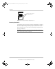
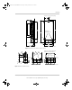
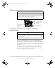
Removing the Wiring Compartment Cover
Before mounting, remove the wiring compartment cover to access the mounting
holes and the wiring terminals. The wiring compartment cover is secured with
two Phillips #8-32 × 2 ½-inch (63.5 mm) screws on the front cover of the unit. See
Figure 2-2.
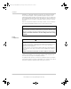
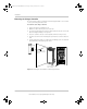
Table 2 - 2 Minimum Clearance Requirements
Location Minimum Clearance
Above 6 inches (150 mm). When units are mounted in a vertical stack,
the topmost unit must maintain the minimum clearance to the
nearest surface.
Note: Minimum clearances can be ignored when mounting two
units on the side of the Conext Power Distribution Panel (PDP).
For more information,
see the Conext XW+ Inverter/Charger
Installation Guide. Other installations must follow the guidelines in
this Guide.
In front Sufficient room to allow for easy access to read the display, to
prevent accidental contact with the heat sink, and to perform
maintenance.
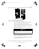
On sides 6 inches (150 mm) on at least one side of the overall assembly. A
maximum of two u
nits can be mounted side by side or side
mounted against a PDP. In both configurations, the minimum
clearance around the outermost unit must be maintained.
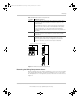
Figure 2-1 Minimum Clearance Requirements
6 inches (150 mm) on top and side(s)
975-0400-01-01_Rev-H(XW-MPPT60-150).book Page 5 Thursday, November 23, 2017 11:48 AM