
Installation Guide


975-0691-01-01 Revision B 2-21
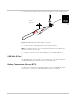
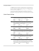
Wiring the Shunt to the Pre-Scaler Board
The Pre-scaler board is connected to the shunt via the twisted wire pair which is
wired to the inner screws on the shunt.
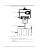
Wiring the Pre-Scaler Board to the Battery Monitor
The Pre-scaler board is connected to the Battery Monitor using the orange RJ45
cable provided. Plug the RJ45 cable directly to the port on the Pre-scaler board
then to the Battery Monitor as indicated in Figure 2-9, “Wiring the Battery Monitor”
on page 2–17.
Wiring the RS 485 Modbus Connector to the Battery Monitor
The RS 485 Modbus connector provides three terminals for communication
cable connections to the Battery Monitor. The three-conductor cable can be 16–
24 AWG with 1.5 mm
2
–0.25 mm
2
wires. The cable can be shielded or non-
shielded.
To wire the RS 485 Modbus connector for data communication:
1. Select a two-wire, twisted pair, shielded cable not longer than 164 ft (50 m).
Refer to the local electrical code and application to select the correct cable
insulation and temperature class.
2. Strip 3/8 in. (10 mm) from the end of the wires to be connected and attach
ferrules to the two signal wires.
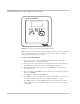
Connect Blue
wire here
Connect Violet
wire here
Figure 2-12 Wiring the shunt to the Pre-scaler board
DANGER
ELECTRIC SHOCK AND FIRE HAZARD
Turn off all other devices prior to wiring the connectors.
Failure to follow these instructions will result in death or serious injury.