
Installation Guide


Modbus Maps
B-60 975-0691-01-01 Revision B
Overview
This appendix describes the structure of the Modbus register address map,
which is used to configure and control the Conext Battery Monitor. The
information in this document is intended for use only by qualified persons who
have a detailed technical understanding of the Modbus protocol.
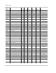
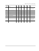
The Modbus map is divided into rows of Modbus registers. Each row indicates
the Modbus register address, its SYSVAR names, Modbus address, Access
types and data types. External Modbus Master devices can read and write the
Modbus registers to configure, control, or monitor the device remotely.
Supported Modbus Data Types
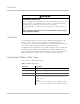
Table 1 lists the supported data types.
WARNING
UNINTENDED OPERATION
The use of this product with Modbus communications requires expertise in the
design, operation, and programming of the device. Only qualified persons
should program, install, alter, and commission this product.
When writing values to the device, ensure nobody else is working with the
device.
Failure to follow these instructions can result in death or serious injury,
and/or equipment damage.
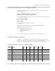
Table 1
Modbus Data Types
Data Type Description
uint16 unsigned 16-bit integer [0,65535]
uint32 unsigned 32-bit integer [0,4294967295]
sint32 signed 32-bit integer [-2147483648,2147483647]
str<nn> packed 8-bit character string, where <nn> is the length of
characters in the string. Two characters are packed into each
Modbus register.
Example:
str20 = 20-character string (packed into 10 Modbus registers)
str16 = 16-character string (packed into 8 Modbus registers)